
Atom-based accelerometer

a technology of accelerometer and atom, applied in the direction of speed/acceleration/shock measurement, measurement devices, instruments, etc., can solve the problems of limited application of atom-interferometric accelerometer, and achieve the effect of reducing the potential energy associated with the interaction

Inactive Publication Date: 2013-06-20
HONEYWELL INT INC
View PDF17 Cites 9 Cited by
  • Summary
  • Abstract
  • Description
  • Claims
  • Application Information

AI Technical Summary

Benefits of technology

The present invention is about trapping and manipulating atoms in a potential well using a combination of rf and dc fields. By keeping the atoms confined during interrogation and using a rf field that is near resonance with the atoms, researchers have been able to achieve long coherence times and low noise relative to other chip-based interferometers. The dc field direction and its interaction with the rf field can be perpendicular or parallel, depending on the configuration of the magnetic field. This allows for precise control of the interaction between the atoms and the fields, making it possible to create precise and accurate measurements. The technical effect of this invention is the ability to trap and manipulate atoms in a potential well with high precision and accuracy using a combination of rf and dc fields.

Problems solved by technology

However, Atom-interferometric accelerometers applications are limited by the size, weight, and power of the apparatus.

Method used


Image

  • Atom-based accelerometer
  • Atom-based accelerometer
  • Atom-based accelerometer

Examples


Embodiment Construction

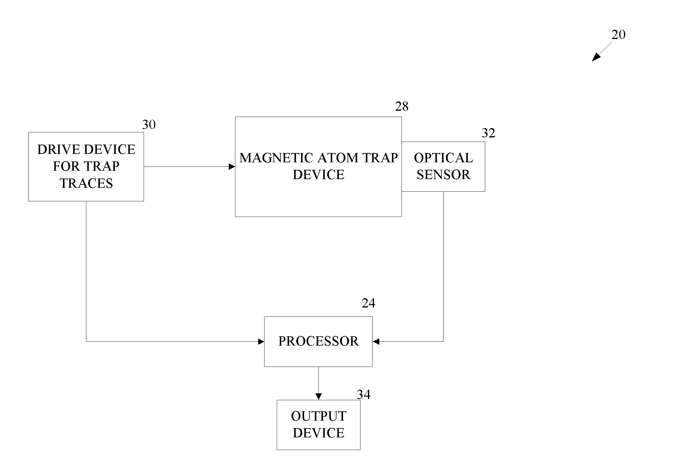
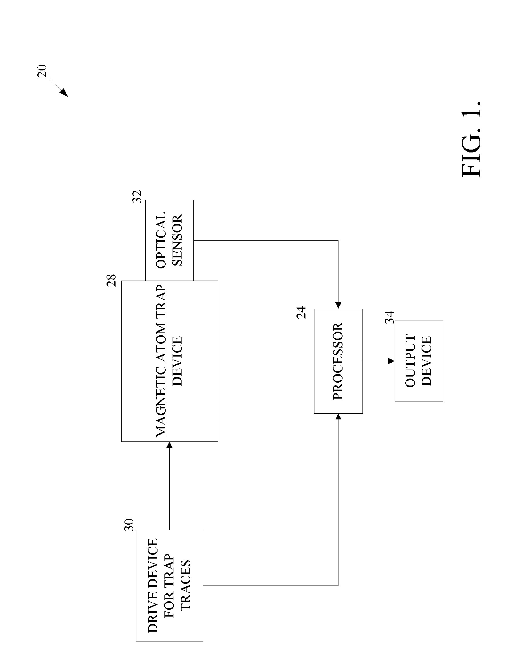
[0018]As shown in FIG. 1, an atom-based accelerometer 20 includes a magnetic atom trap device 28 located at least partially within a vacuum. The atom-based accelerometer 20 also includes an optical sensor 32, a processor 24, a drive device 30 and an output device 34.

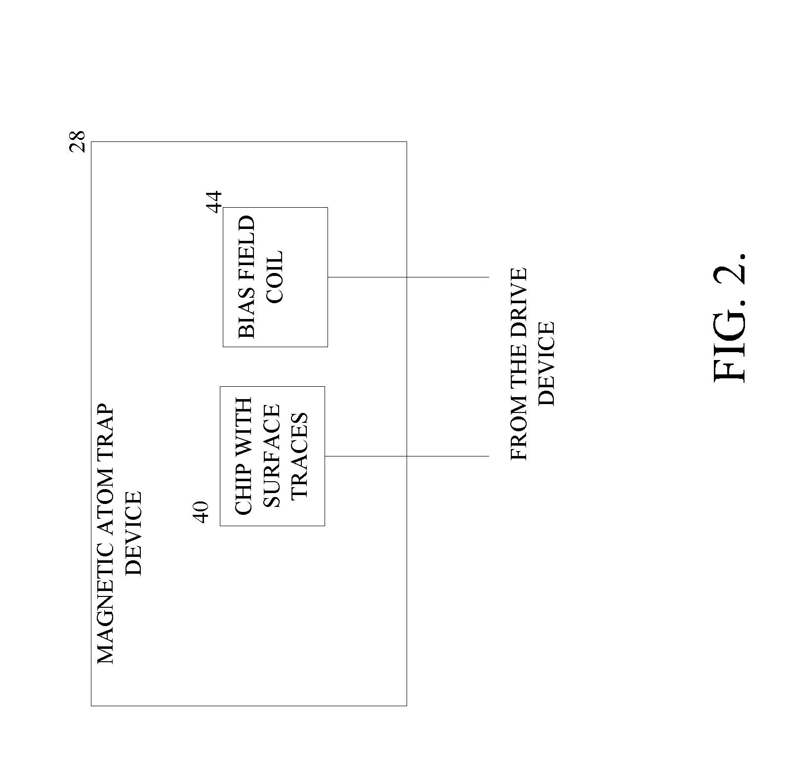
[0019]The drive device 30 applies radio frequency (rf) current (signal) and / or an alternating current (AC) to traces on a chip 40 within the trap device 28 according to instructions from the processor 24 (FIG. 2). Atoms are manipulated by magnetic fields produced by the traces. At a certain point in time, the optical sensor identifies a phase of the atoms then the processor 24 determines an acceleration (or ΔV) value based on the phase of the atoms and sends the results to the output device 34.

[0020]FIG. 3 shows an exemplary process 70 performed by the atom-based accelerometer 20. First an atomic Bose-Einstein condensate is prepared from a cold atom sample collected and storied in a Magneto Optical Trap (MOT) using metho...


PUM


Abstract

An atom-based accelerometer for measuring acceleration or gravity with an interaction region less than a millimeter in size. An exemplary device includes a magnetic double-well trap produced on a chip. Creation and dissolution of the double-well trap is provided by interaction between an ac magnetic field and a radio frequency (rf) magnetic field produced by traces on the chip.

Description

BACKGROUND OF THE INVENTION[0001]The best rate gyros currently commercially available are based on the optical Sagnac effect, which takes place either in an active laser cavity or in a passive fiber interferometer. In the first case, the products are known as gyrolasers and, in the second, fiber-optic gyros (FOGs). The replacement of the optical waves by matter waves leads to a huge gain in sensitivity, even if the latter is, in part, counterbalanced by the reduction in the signal-to-noise ratio and in the area of the interferometer. Matter-wave gyros have been an experimental reality since 1997, the date of the first measurement of the Earth's rotation with this type of device. Today, several laboratories have constructed similar sensors, and the performances attained already surpass those of the best optical gyros. For future developments, the potential for improvement is still several orders of magnitude. Atom-interferometric accelerometers and gravimeters currently achieve nano-...

Claims


Application Information

Patent Timeline
IPC IPC(8): G01P15/00
CPCG01P15/093G01P15/08
Inventor SACKETT, CHARLESSALIT, MARYSALIT, KENNETHCOMPTON, ROBERT
Owner HONEYWELL INT INC
Learn More