Apparatus and method for coating glass substrate

a technology of glass substrate and apparatus, which is applied in the direction of spraying apparatus, coating, induction-charging spraying, etc., can solve the problems of slow coating growth rate, difficult control of the uniformity of the produced coating, and limited utilization of the coating process. achieve the effect of high coating growth rate, and high coating growth ra

Inactive Publication Date: 2013-06-27
BENEQ OY
View PDF11 Cites 11 Cited by
  • Summary
  • Abstract
  • Description
  • Claims
  • Application Information

AI Technical Summary

Benefits of technology

[0008]The present invention is based on an idea of supplying the starting materials into the deposition chamber as liquid droplets and directing the droplets towards the surface of the glass substrate to be coated. The deposition chamber is further provided with at least one thermal reactor for vaporizing the droplets before the droplets contact surface of the glass substrate or before the starting materials react on the surface of the substrate. The thermal reactor may be produced with a flame or with plasma or as a hot zone produced with heating means, such as electrical heating means. Preferable the thermal reactor is provided substantially close to the surface of the substrate. In an other embodiment the glass substrate is brought to the coating process in such a temperature that the thermal energy of the glass substrate is able to produce a hot zone and vaporize the droplets substantially close to the surface of the glass substrate. The vaporized starting materials react on the substrate surface to produce a desired coating or film on the substrate. As the starting materials are vaporized close to the substrate surface, the vapour pressure of the starting materials at the substrate surface is high, thus

Problems solved by technology

The problem in the above identified prior art coating process is the slow growth rate of the coating, which is due to fact that the liquid droplets brought to the surface of the glass produce a liquid film on the surface of the glass.
The slow growth rate limits the utilization of this coating process in many applications such as when a coating is produced on a moving sheet glass.
Furthermore, the uniformity of the produced coating is difficult to control in this prior art coating process as uniformity of the produced coating depends on the uniform deposition of the droplets on the

Method used


Image

  • Apparatus and method for coating glass substrate
  • Apparatus and method for coating glass substrate
  • Apparatus and method for coating glass substrate

Examples


first embodiment

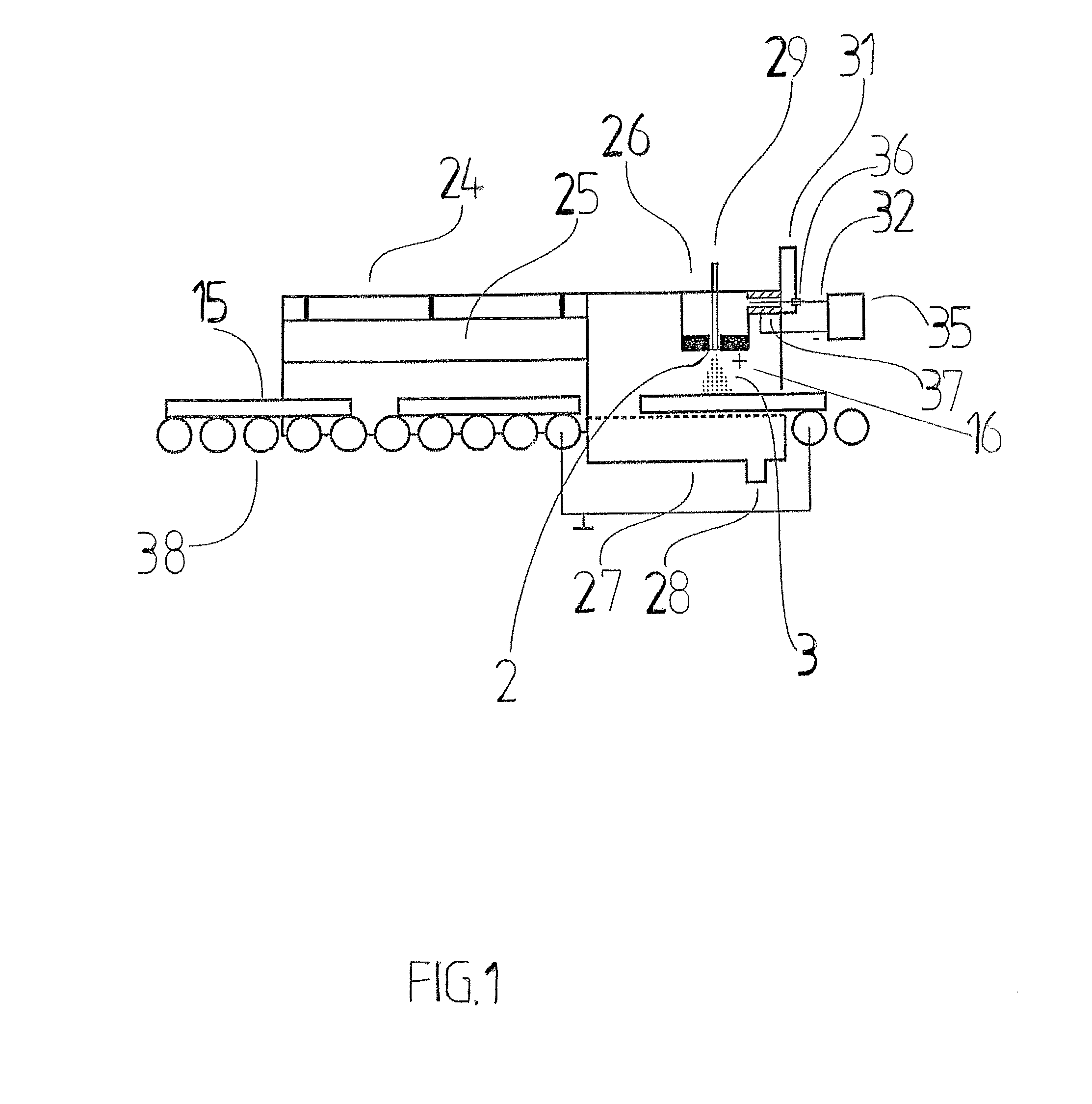
[0017]FIG. 1 shows, in principle, the invention, where the formation of a coating on a of glass substrate 15 is carried out in a coating apparatus. Flat glass substrate 15, with a typical size of 1100 mm×1400 mm, moves from right to left. The glass substrate 15 first enters a heating furnace 24 including a heater 25. The heater 25 may be based on radiation, convection or similar. In the heating furnace 24 the glass substrate 15 heats to a temperature which is higher than the annealing point (annealing temperature) of the glass substrate 15. The annealing point depends on the composition of glass substrate 15 and is typically about 500° C. for soda-lime glass and about 1100° C. for fused silica. The glass substrate 15 then enters the coating unit 26 where droplets 3 are deposited on the glass substrate 15 or guided towards the glass substrate 15 in a deposition chamber 16. An air floating device 27 floats the glass substrate 15 by a gas blowing motion, the gas being fed through condu...

second embodiment

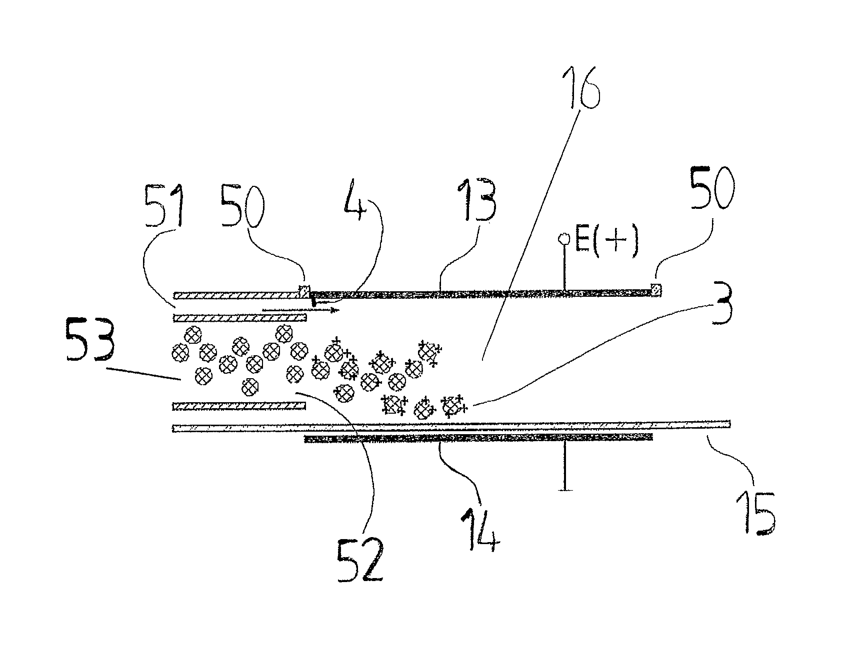
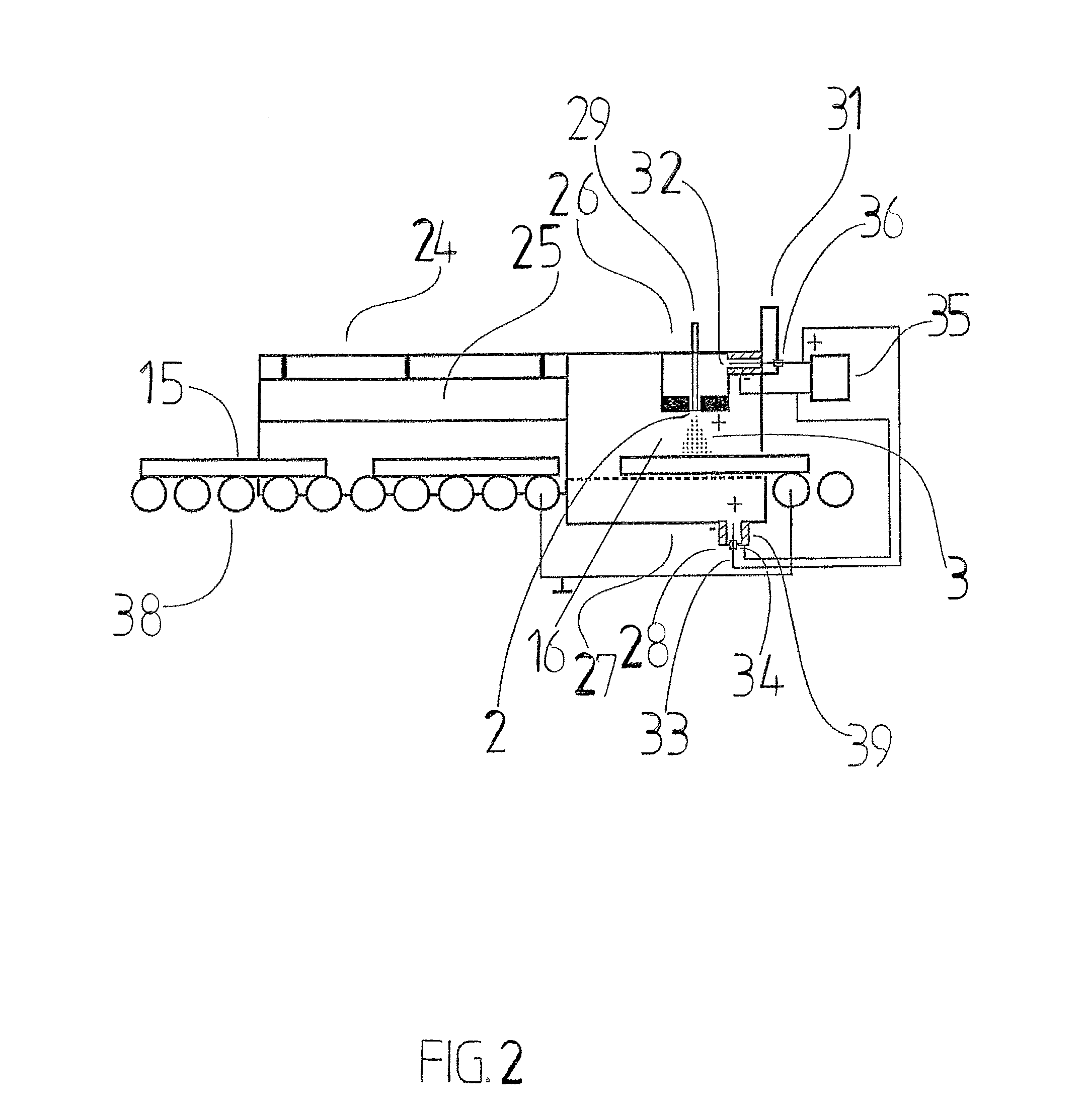
[0019]FIG. 2 shows, in principle, the invention where the glass heating movement and coating is carried out in the same way as with the previous embodiment shown in FIG. 1. In addition a second corona charger 33 is used to charge the air used in the air floating device 27. The second corona electrode 33 is equipped with a second an electrical insulator 34 and with a second counter electrode 39. FIG. 2 shows an embodiment where the second corona charger 33 uses the same power supply 35 as the first corona charger 32. It is, however, obvious for a person skilled in the art that also another power supply, with different voltage, may be used. It is essential to the invention that the air supporting the glass substrate 15 charges the bottom surface of the glass substrate 15 with the same polarity as the droplets 3 are charged. The rejection force caused by the charges with same polarity decreases the formation of the coating to the bottom surface of the glass substrate 15. Obviously, als...

third embodiment

[0020]FIG. 3 shows, in principle, the invention where the electrostatic forces for the droplet deposition and guiding are enhanced by charging the top surface of the glass substrate 15 with a charge opposite to the charge of the droplets 3. Preferably the charging is carried out by charging air passing through the conduit 40 by a third corona charger 41. The third corona charger 41 is provided a third electrical insulator 42 and with a third counter electrode 43. As shown in FIG. 3, the third corona charger 41 has an opposite polarity to the first corona charger 32. FIG. 3 shows an embodiment where the third corona charger 41 uses the same power supply 35 as the first corona charger 32. It is, however, obvious for a person skilled in the art that also another power supply, with different voltage, may be used.

[0021]FIG. 4, shows, in principle, a fourth embodiment where a separate electric field is used to enhance the deposition or guiding of the charged droplets 3. The droplets 3 are...


PUM

PropertyMeasurementUnit
Fractionaaaaaaaaaa
Forceaaaaaaaaaa
Energyaaaaaaaaaa

Abstract

A method and apparatus for coating a substrate using one or more liquid starting materials. The substrate is coated by atomizing one or more liquid starting materials into droplets and vaporizing the droplets in a deposition chamber for before the starting materials react on the surface of the substrate. The droplets are guided towards the substrate with electrical forces before the droplets are vaporized.

Description

FIELD OF THE INVENTION[0001]The present invention relates to an apparatus for coating a glass substrate and more particularly to an apparatus according to the preamble of claim 1. The present invention further relates to a method for coating a glass substrate and more particularly to a method according to the preamble of claim 18.BACKGROUND OF THE INVENTION[0002]It is generally know to use liquid starting materials for coating glass by atomizing the liquid starting materials into droplets and directing the formed droplets on the surface of glass to be coated for producing a coating. In other words according to the prior art the droplets are brought to the surface of the substrate to be coated as liquid droplets, whereby the coating is formed on the surface of the substrate such that first the droplets brought on the surface are pyrolized or the vaporizable substances of the droplets are vaporized for providing a coating on the surface of the substrate.[0003]The problem in the above ...

Claims


Application Information

Patent Timeline
IPC IPC(8): C03C17/00
CPCB05B5/03B05B5/043C03C17/001C23C16/4486C23C16/545C03C17/002B05B5/005C23C16/452
Inventor RAJALA, MARKKUJANKA, KAUKOKAUPPINEN, SAMIHOVINEN, ANSSI
Owner BENEQ OY
Why Eureka
Try Eureka