
3D porous material comprising machined side

a technology of porous materials and machined sides, applied in the field can solve the problems of difficult machining or cutting of 3d porous materials with a porosity of more than 80%, damage to the surface of 3d porous materials after cutting, and difficulty in obtaining maximum contact, etc., to achieve improved heat transfer effect, high quality cut, and increased surface area

Inactive Publication Date: 2013-07-04
UNIV GENT
View PDF1 Cites 14 Cited by
  • Summary
  • Abstract
  • Description
  • Claims
  • Application Information

AI Technical Summary

Benefits of technology

The patent describes a method for creating a smooth and highly accessible surface on the machined side of a metal foam material used in heat exchangers. This surface has minimal bumps, holes, or material melting. The tube used in the heat exchanger can be either a flat or round tube that matches the smooth surface of the metal foam. This results in improved heat conduction and convection.

Problems solved by technology

Using conventional cutting methods like band sawing, the surface of 3D porous material after cutting is damaged.
With conventional cutting technology, it is difficult to obtain maximum contact.
It has been noticed that machining or cutting of 3D porous materials with a porosity of more than 80% is not easy, as in some instances material is lost or material is bent or compressed or even locally melted.
Commonly such 3D porous materials are cut by heated wire for polymer materials, and common circular saw or band saw for metal materials; to get the desired shape, for e.g. heat exchanger, sandwich panel, . . . . The cut surface of such 3D porous materials tends to be uneven and unpredictable due to the high porosity which makes the cutting or machining process difficult.

Method used


Image

  • 3D porous material comprising machined side
  • 3D porous material comprising machined side
  • 3D porous material comprising machined side

Examples


first embodiment

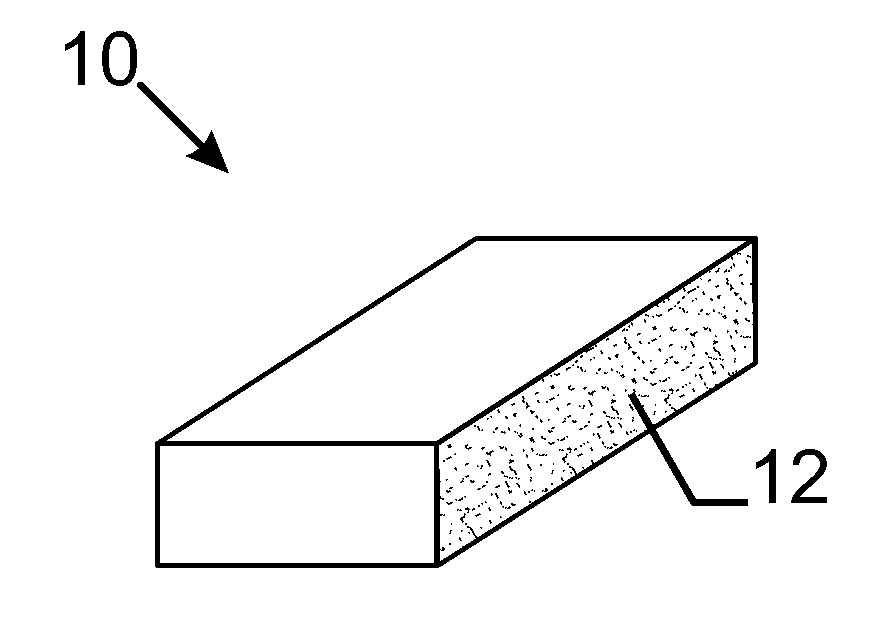
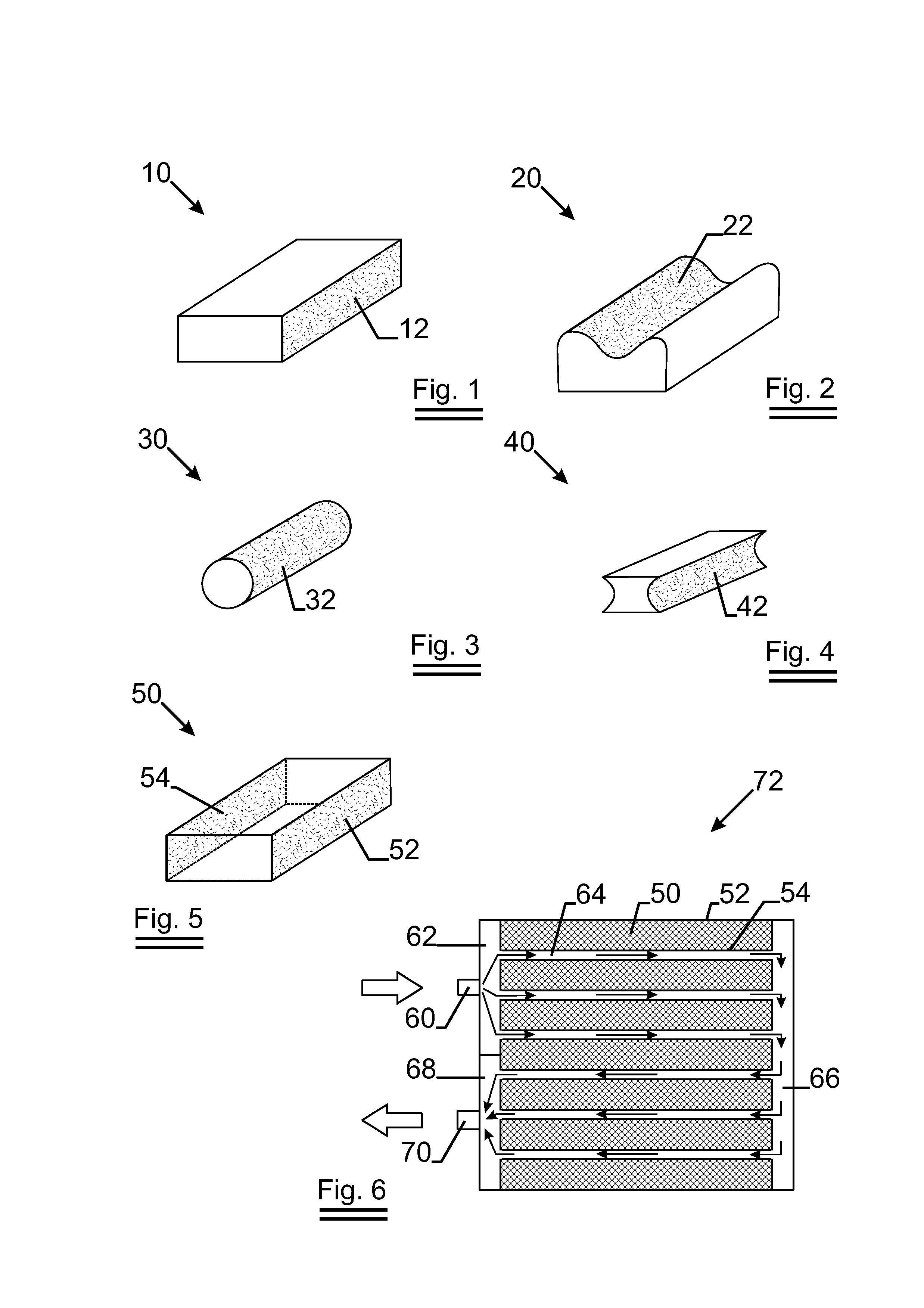
[0063]FIG. 1 illustrates the present invention. Open cell metal foam 10 made of aluminium has a machined side 12 which has a substantially flat surface. The solid percent Ps of the machined side 12 is 6.1% while the porosity Po of open cell metal foam 10 is 94%. PPI of open cell metal foam 10 is 10 ppi.

[0064]To get the machined side 12, open cell metal foam 10 which is formed by casting aluminium in a known way is cut by fixed abrasive sawing wire which has a diameter of 250 micron and a tensile strength of 2200N / mm2.

second embodiment

[0065]FIG. 2 illustrates the present invention. Closed cell metal foam 20 which is made of aluminium has a machined side 22. The machined side has a curved surface. The solid percent Ps of the machined side 22 is 40.3% while the porosity Po of closed cell metal foam 20 is 60%.

third embodiment

[0066]FIG. 3 illustrates the present invention. Open cell metal foam 30 made of copper has a machined side 32. The machined side 32 is circular. The solid percent Ps of the machined side 32 is 7.5% while the porosity Po of open cell metal foam 30 is 93%. PPI of open cell metal foam 30 is 20 ppi.


PUM

PropertyMeasurementUnit
porosityaaaaaaaaaa
porosityaaaaaaaaaa
distanceaaaaaaaaaa

Abstract

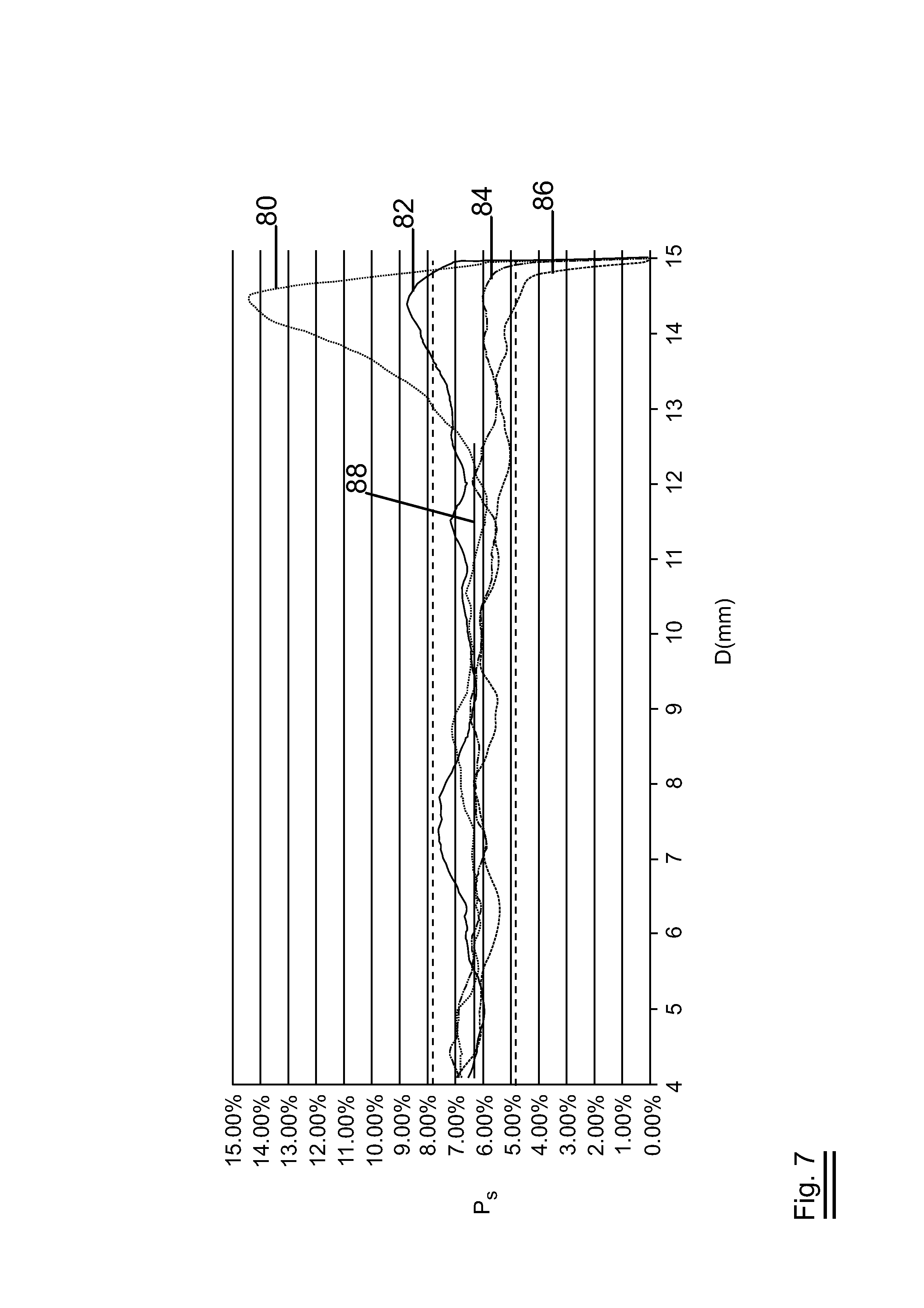
3D porous material comprises at least one machined side. The machined side has a solid percentage Ps being (1−Po), said Po is the porosity of the bulk of said 3D porous material and said Ps is within the 99.5% confidence interval. The present invention provides the method of manufacturing such 3D porous material. Preferably, the 3D porous material is open cell metal foam. The present invention also provides use of such open cell metal foam in a heat exchanger. The present invention further provides a heat exchanger comprising open cell metal foam.

Description

TECHNICAL FIELD[0001]The present invention relates to 3D porous material, preferably made of metal; more specific the processing of such 3D porous material pieces.[0002]More in particular, the invention relates to open cell 3D porous metal material, preferably open cell metal foam, and method to cut such open cell 3D porous metal material. Furthermore, the invention also relates to use of open cell 3D porous metal material in a heat exchanger.[0003]The invention further relates to a heat exchanger, heat sink (thermal energy exchanging device in general) comprising open cell 3D porous metal material, preferably open cell metal foam.BACKGROUND ART[0004]3D porous materials, with a porosity of 80% or more, are used in many industrial and consumer applications. Examples of such 3D porous materials comprise honeycomb structures in polymer or metal materials, open and closed cell foam in polymer or metal materials, a carbon or graphite foam; a carbon or graphite containing metal foam; open...

Claims


Application Information

Patent Timeline
Patent Type & Authority Applications(United States)
IPC IPC(8): F28F21/08B23D45/00B24B1/00
CPCC22C1/08F28F13/003B23D45/00Y10T428/12479F28F21/08Y10T428/24479B24B1/00Y10T83/04Y10T428/249921
Inventor HUGELIER, JOHANDE JAEGER, PETERPRIEM, JOHAN
Owner UNIV GENT
Learn More