
Reaction device for producing hydrocarbons from synthesis gas

a technology of reaction device and hydrocarbon, which is applied in the direction of liquid-gas reaction process, hydrocarbon oil treatment, chemistry apparatus and processes, etc., can solve the problems of high hydrogen ratio, long life span, and high price of cobalt catalyst, and achieve the effect of stably promoting xtl

Inactive Publication Date: 2013-07-04
KOREA RES INST OF CHEM TECH
View PDF3 Cites 5 Cited by
  • Summary
  • Abstract
  • Description
  • Claims
  • Application Information

AI Technical Summary

Benefits of technology

The patent text describes a new technology that allows for the recirculation of particles during a chemical reaction, which helps to prevent the particles from sticking together and forming larger aggregates. This results in a more efficient and reliable process for producing certain products. The technology also includes a separating device to remove any unreacted particles, which further improves the quality of the final products. Overall, this technology advancement helps to promote the development and production of new products more effectively.

Problems solved by technology

However, when a ratio of hydrogen is high, selectivity of methane is increased, so that selectivity of C5+ (hydrocarbon with 5 carbon atoms or more) is relatively decreased, the high ratio of the hydrogen is not appropriate.
Compared to this, the cobalt catalyst mainly generates liquid fuels, generates less carbon dioxide, and has a long life span.
However, the cobalt catalyst is very high in price than iron, methane selectivity thereof is increased, so that the cobalt catalyst needs to be reacted at a low temperature, and the cobalt catalyst is high in price, so that it is necessary to use the cobalt catalyst by distributing well a small amount of cobalt catalyst on a surface of a support.
As described above, various catalyst particle separation methods have been disclosed, but there is a limit in that the catalyst is separated only by the filtration method because fine catalyst particles or fragmented catalyst particles during a slurry reaction block fine filter holes.
Further, there is a disadvantage in that the centrifugal separator has a burden in operating a rotation device, and a sedimentation method takes a long time.
The magnetic separation method is an effective method, but is very high in price and an applicable catalyst is limited to a few kinds of catalysts.
Further, according to the U.S. Pat. No. 5,977,192, a problem was found in that a agglomeration phenomenon is generated due to a contact with liquid hydrocarbon when fine catalyst particles with less than 20 μm are injected to the reactor so that the catalyst particles are not distributed well inside the reactor, and process performance was improved by adding alcohol, ketone, ester, ether, or a mixture thereof, which is liquid polar oxygenate, not acidic.
A method of suppressing agglomeration by adding an additional additive like the aforementioned methods is highly preventive to be helpful for a fundamental solution, but the fact is obvious that the catalyst is fragmented due to accumulation of catalyst fatigue caused by a long-time operation or it is impossible to completely prevent fine catalyst particles, which are inevitably inserted at a predetermined portion when an additional catalyst is injected, from being aggregated.
In addition, it is necessary to consider increase in an expense and other additional problems generated by injecting an additional compound during the process, and the large amount of expense is caused by separating and refining a tiny amount of compound even though the alcohol with the high boiling point or the polar oxygenate is replaced with similar kinds of by-products co-produced during a producing process.

Method used


Image

  • Reaction device for producing hydrocarbons from synthesis gas
  • Reaction device for producing hydrocarbons from synthesis gas
  • Reaction device for producing hydrocarbons from synthesis gas

Examples


Embodiment Construction

Technical Problem

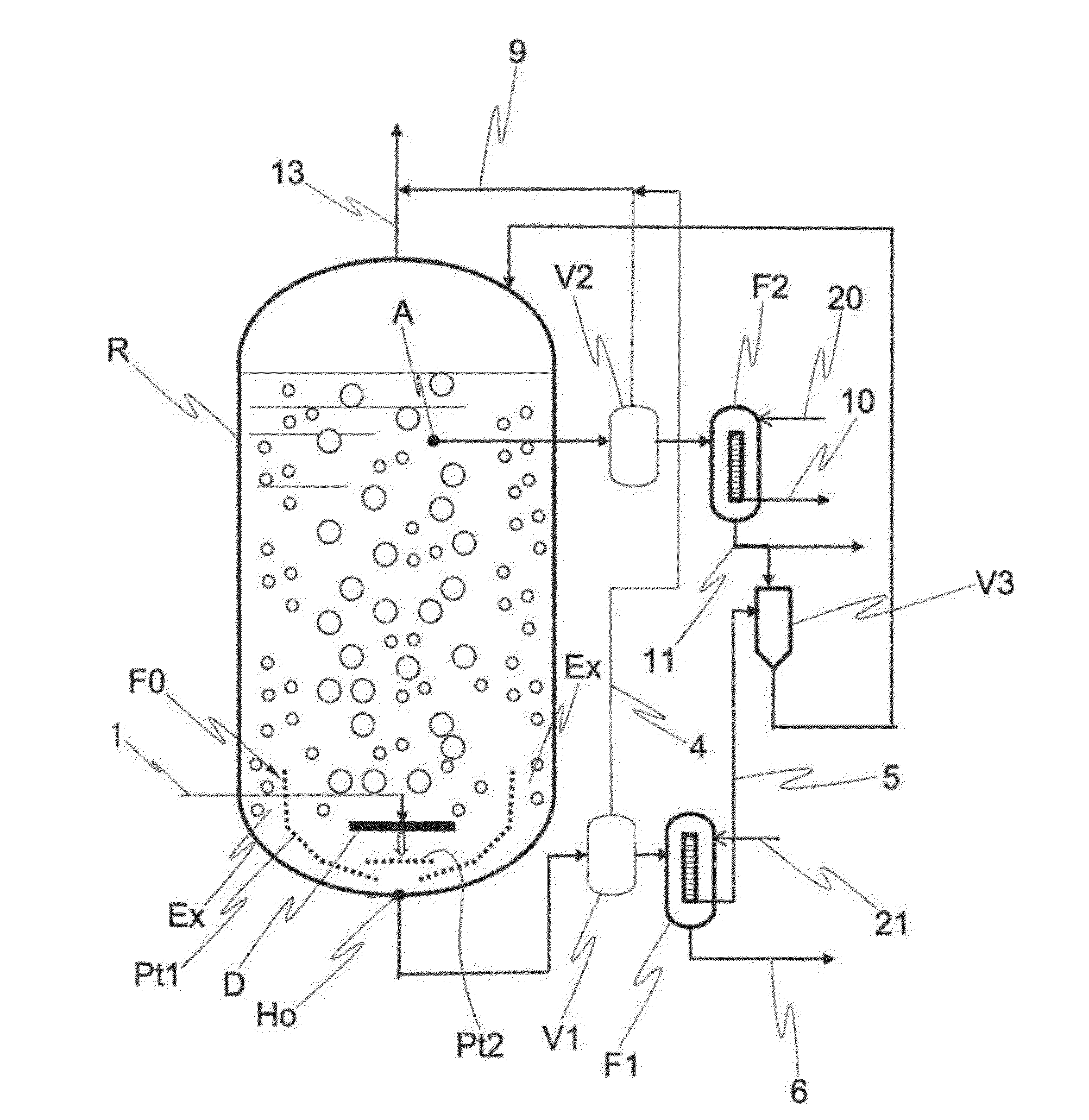
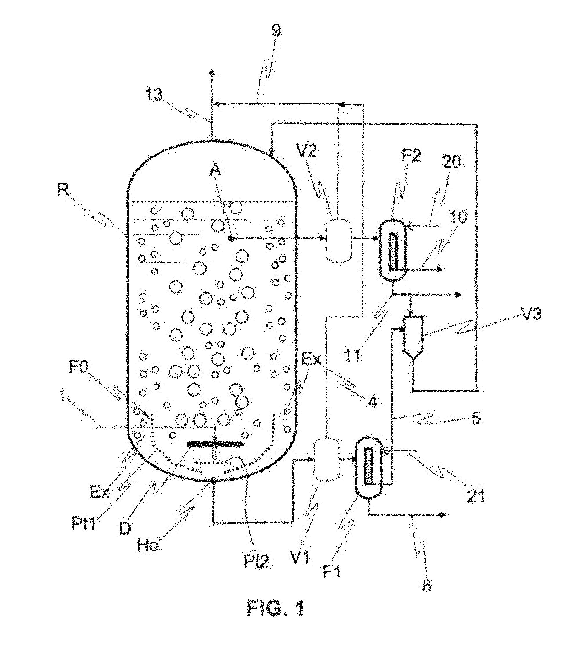
[0019]The present invention is a result researched in order to solve a agglomeration phenomenon of the catalyst particles, which occurs in the slurry phase reactor and the catalyst separation method using the same in the related art, and an object thereof is to provide a reaction device for producing hydrocarbons from synthesis gas, in which an internal filter system for separating enlarged catalyst lumps due to the agglomeration is installed inside the reactor, and a separating device is separately disposed outside, such that it is possible to recirculate only particles having a size appropriate for performing F-T synthesis in the slurry phase, and additionally, it is possible to effectively discharge and process catalyst lumps aggregated due to a combination of fine catalyst particles, the fragmented catalyst particles, and the like with liquid hydrocarbon, co-produced water, and the like in the slurry phase reactor.

Technical Solution

[0020]In order to achieve the ...


PUM


Abstract

Disclosed is a reaction device for producing hydrocarbons from synthesis gas, in which hydrocarbons, olefins, oxygenates, etc., are produced over a Fischer-Tropsch catalyst by using synthesis gas, so that catalyst particles can easily be from a slurry which is discharged to the outside. That is, the present invention provides a reaction device for producing hydrocarbons from synthesis gas, in which an internal filter system for separating particles enlarged due to a agglomeration phenomenon of a catalyst is installed inside the reactor, and an separating device is separately disposed outside, such that it is possible to recirculate only particles having a size appropriate for performing F-T synthesis in the slurry phase, and additionally, it is possible to effectively discharge and process a catalyst aggregated due to a combination of fine catalyst particles, the catalyst chipped off during the operation, etc., liquid hydrocarbon, resulting water, etc., in the slurry phase reactor.

Description

TECHNICAL FIELD[0001]The present invention relates to a reaction device for producing hydrocarbons from synthesis gas, and more particularly, to a reaction device for producing hydrocarbons from synthesis gas, in which hydrocarbons, olefins, oxygenates, and the like are produced over a Fischer-Tropsch catalyst by using synthesis gas, in such a way that catalyst particles can easily be from a slurry which is discharged to the outside.BACKGROUND ART[0002]By the F-T synthesis method developed by Fischer and Tropsch, who are German chemists in 1923, it is possible to produce liquid hydrocarbon from coal, natural gas, biomass, and the like through synthesis gas. A process of producing liquid hydrocarbon from coal is referred to as a coal-to-liquids (CTL) process, a process of producing liquid hydrocarbon from natural gas is referred to as a gas-to-liquids (GTL) process, and a process of producing liquid hydrocarbon from biomass is referred to as a biomass-to-liquids (BTL) process, and si...

Claims


Application Information

Patent Timeline
Patent Type & Authority Applications(United States)
IPC IPC(8): B01J8/00
CPCB01J8/006B01J8/226B01J8/228B01J2208/00902C10G2300/1022B01J2208/00938B01J8/0085C10G2/32C10G2/342B01J2208/00929B01J8/22
Inventor HA, KYOUNG SUKIM, DU EILJUNG, GYU INBAE, JONG WOOKJUN, KI WON
Owner KOREA RES INST OF CHEM TECH
Learn More