Part solid, part fluid and flow electrochemical cells including metal-air and li-air battery systems

a technology of fluid electrochemical cells and electrochemical cells, applied in the direction of electrochemical generators, cell components, indirect fuel cells, etc., can solve the problems of major scale up problems, limited 3-dimensional design of batteries, and inability to meet the needs of large-scale applications, so as to increase the safety and/or performance of batteries

Pending Publication Date: 2013-07-25
CALIFORNIA INST OF TECH
View PDF4 Cites 122 Cited by
  • Summary
  • Abstract
  • Description
  • Claims
  • Application Information

AI Technical Summary

Benefits of technology

[0052]In an embodiment, a three-dimensional electrode array further comprises one or more metal, glass, ceramic, steel or polymer plates including an array of apertures, wherein the one or more metal, glass, ceramic, steel or polymer plates are arranged in a substantially parallel orientation such that the each aperture of an individual metal, glass, ceramic, steel or polymer plate is aligned along the alignment axis passing through the apertures of each of the plate electrodes. Such metal, glass, ceramic, steel or polymer plates are useful, for example, for providing structural integrity to the three-dimensional electrode array. In an embodiment, the electrode array further comprises one or more insulating plates comprising an electrically insulating material and having a plurality of apertures for passing the rod electrodes. In an embodiment, for example, the insulating plates are provided between adjacent plate electrodes of the array and in an orientation such that the apertures accommodate the rod electrodes of the array. In an embodiment, for example, electrically insulating plates are interleaved between adjacent plate electrodes to prevent shorting between adjacent plate electrodes.
[0055]In an embodiment, a three-dimensional electrode further comprises one or more desiccant plates including an array of apertures and comprising a desiccant selected from the group consisting of silica gel, activated charcoal, calcium sulfate, calcium chloride, montmorillonite clay, molecular sieves and any combination of these, wherein the one or more desiccant plates are arranged in a substantially parallel orientation such that the each aperture of an individual desiccant plate is aligned along the alignment axis passing through the apertures of each of the plate electrodes. Optionally, one or more desiccant plates comprise an inert coating or a PTFE coating. Inert coatings or PTFE coatings are useful, for example, when the three-dimensional electrode array is a Li battery and / or a part solid, part fluid electrochemical cell, such as a metal-air battery system including a lithium-air battery or zinc-air battery, or a metal-aqueous battery system, such as a lithium-water battery. Optionally, the inert coating or PTFE coating increases the safety and / or performance the battery. In certain embodiments, a desiccant plate is removed from the three-dimensional electrode array after the desiccant plate is saturated with water.
[0075]Optionally, a redox flow battery further comprises an anode in a catholyte compartment, a cathode in an anolyte compartment and, an ion selective membrane separator between the compartments, a pair of electrolyte reservoirs, one for anolyte and the other for catholyte, and electrolyte supply means for circulating anolyte from its reservoir, to the anolyte compartment in the cell and back to its reservoir and like circulating means for catholyte; the battery comprising: connections to its electrolyte reservoirs and / or its electrolyte supply means so that the battery can be recharged by withdrawing spent electrolyte and replacing it with fresh electrolyte. Optionally, an electrolyte divider or membrane is a diaphragm between each rod and the walls of the corresponding holes, or a thin tube shape that the inner and outer radii are chosen to fit between the rod and the corresponding wall and is as long as each of the rods or a thin tube shape as long as the thickness of each of the perforated plates.

Problems solved by technology

These structures, however, may not be the best answer to be applied to part solid-part fluid electrochemical cells such as in metal air batteries or lithium water batteries or semi-solid batteries or metal-metal based redox flow couple batteries.
Further, these so called 3-dimensional designs of the batteries are limited to very small scales and have major problems to scale up both in terms of the fabrication time and cost and also technology limitations, Chem. Rev. 2004, 104, 4463-4492, J. Mater. Chem., 2011, 21, 9876, Nano Lett., 2012, 12 (3), pp 1198-1202, http: / / hdl.handle.net / 10062 / 25375.
Most of these batteries are also limited to use solid electrolytes such as by conformal coating.
However, the high viscosity of semi-solid electrodes may result in the need for strong pumps which can cause energy losses.
This further limits the size of the cells, especially due to inhomogeneous heat and electric (electronic and ionic) conductivities of the parallel plate design.
However, the high viscosity of semi-solid electrodes may result in the need of strong pumps which can cause energy losses.
This further limits the size of the cells, especially due to inhomogeneous heat and electric (electronic and ionic) conductivities of the parallel plate design.
Current electrochemical systems such as batteries, especially at high charging-discharging rates may lose their cycle life earlier than is needed by some applications.
The current parallel plate design of electrochemical cells can result in uneven distribution of heat inside the cell, especially in thicker cells.
The temperature inhomogeneity inside a cell and the electrodes can result in shorter life cycles by mechanisms such as hot spots.
This may even result in failure of the cell that in some cases can cause fires and explosions and can be hazardous.
One major drawback of current parallel plate electrochemical cells is the loss of performance, especially energy density and power density, when making packs and modules by connecting cells in parallel and series.
However, it is generally a difficult task to place a reference electrode in a parallel plate cell.

Method used


Image

  • Part solid, part fluid and flow electrochemical cells including metal-air and li-air battery systems
  • Part solid, part fluid and flow electrochemical cells including metal-air and li-air battery systems
  • Part solid, part fluid and flow electrochemical cells including metal-air and li-air battery systems

Examples


example 1

Industrial Applications

[0288]Worldwide, there are ever-growing demands for electricity. At the same time, there is an increasing push to harness reusable sources of energy to help meet these increasing electricity demands and offset and / or replace traditional carbon-based generators which continue to deplete natural resources around the world.

[0289]Many solutions have been developed to collect and take advantage of reusable sources of energy, such as solar cells, solar mirror arrays, and wind turbines. Solar cells produce direct current energy from sunlight using semiconductor technology. Solar mirror arrays focus sunlight on a receiver pipe containing a heat transfer fluid which absorbs the sun's radiant heat energy. This heated transfer fluid is then pumped to a turbine which heats water to produce steam, thereby driving the turbine and generating electricity. Wind turbines use one or more airfoils to transfer wind energy into rotational energy which spins a rotor coupled to an el...

example 2

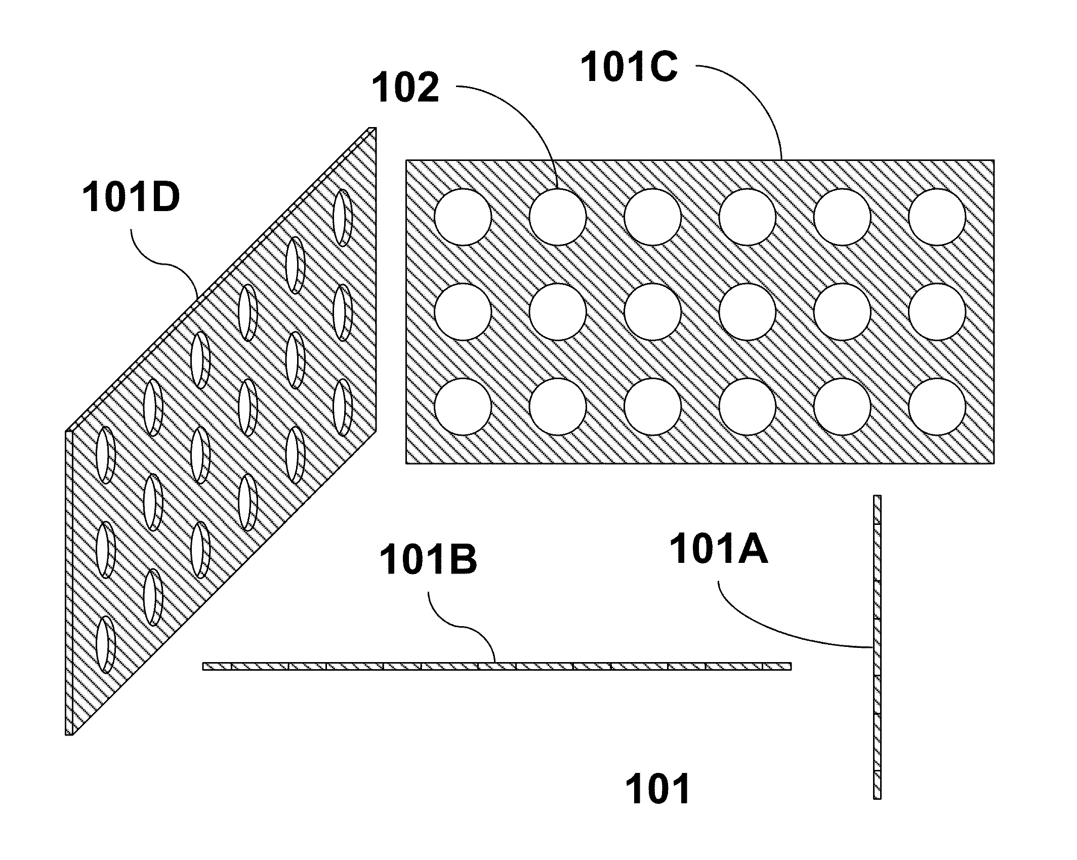
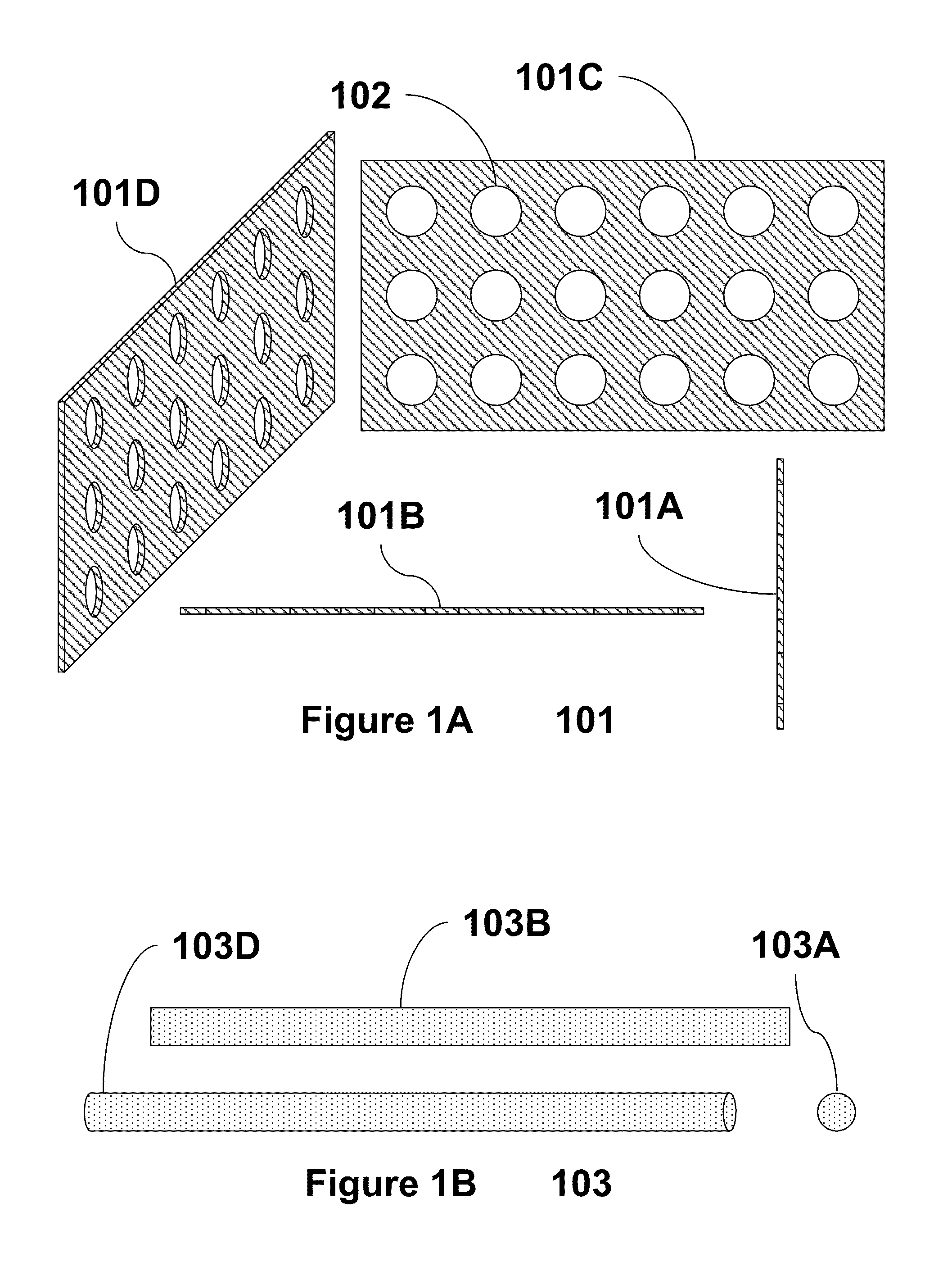
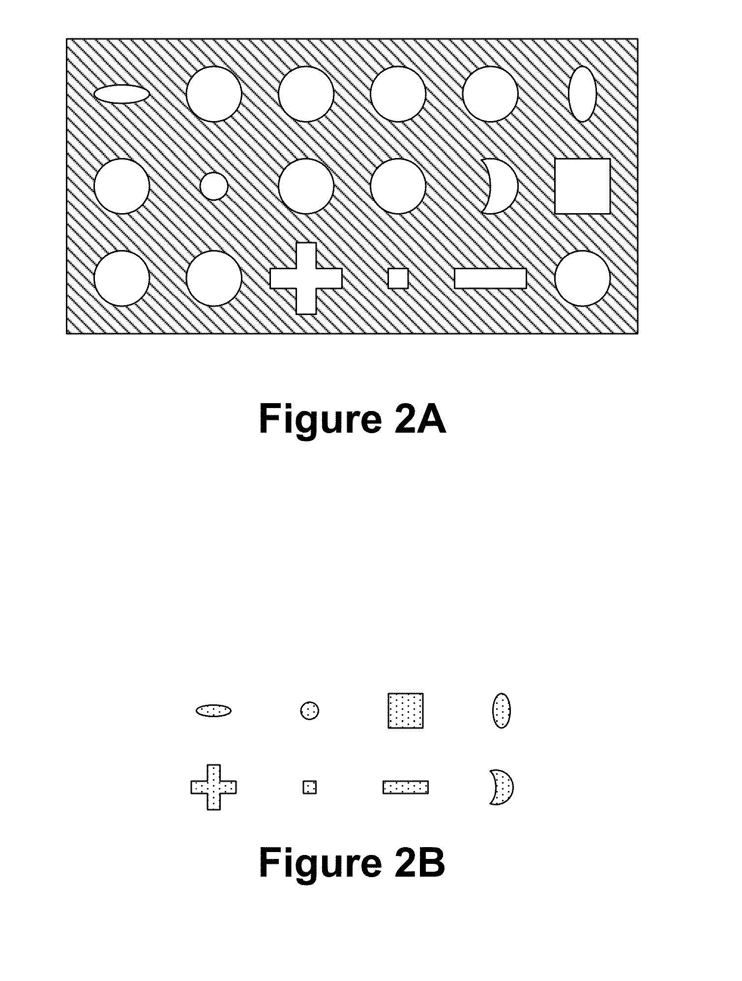
Electrochemical Cells

[0308]Many scientists have been working on the chemistry of batteries. This example describes a new configuration for the electrodes that can be used for any chemistry, including anode, cathode and electrolyte, which can result in higher power / energy density batteries, faster batteries, lighter batteries, cheaper batteries, and more durable batteries.

[0309]In designing the most historically successful industrial batteries, the lead-acid battery configuration played a key role. Plante's and Faure's changes of the configurations resulted in the commercialization of lead-acid battery which has been the dominant battery for more than a century.

[0310]The new configuration described here can be used for primary and secondary batteries. It can transform primary batteries to secondary batteries and it can provide better cyclability and safety for secondary batteries. As an example, the new configuration can be used for primary and secondary lithium batteries. Lithium me...

example 3

Lithium Batteries

[0314]This example focuses on lithium batteries. A great degree of attention has been devoted to rechargeable Lithium batteries in the past few years, but still there are many unknowns that should be scrutinized. Here, a new configuration of the electrodes is described. As an example a Li-metal anode is considered. Lithium metal used as an anode active material has a very high theoretical capacity of 3860 Ah / kg, which is the highest among metallic anode materials. In addition, the standard electrode potential of lithium is high (−3.045V vs SHE). This makes lithium metal a very attractive anode material.

[0315]Because of safety problems, a safer lithium cell, the lithium ion cell, was developed and is now commercially available. Currently Li-metal anodes are only used in primary lithium batteries. They can't be used in rechargeable cells due to the lithium dendrites that form on the lithium metal anode in the recharging process. The dendrites make shorts between the o...


PUM

PropertyMeasurementUnit
porosityaaaaaaaaaa
electrochemical oxidation/reduction potentialaaaaaaaaaa
thicknessaaaaaaaaaa

Abstract

The invention provides part solid, part fluid and flow electrochemical cells, for example, metal-air and lithium-air batteries and three-dimensional electrode arrays for use in part solid, part fluid electrochemical and flow cells and metal-air and lithium-air batteries.

Description

CROSS-REFERENCE TO RELATED APPLICATIONS[0001]This application is a continuation-in-part of U.S. nonprovisional patent application Ser. No. 13 / 229,479, filed Sep. 9, 2011, which claims the benefit of, and priority to, U.S. Provisional Application No. 61 / 381,400, filed on Sep. 9, 2010, U.S. Provisional Application No. 61 / 416,193, filed on Nov. 22, 2010, and U.S. Provisional Application No. 61 / 467,112 filed on Mar. 24, 2011; and this application also claims the benefit of, and priority to, U.S. Provisional Application No. 61 / 598,467, filed Feb. 14, 2012, U.S. Provisional Application No. 61 / 607,324, filed Mar. 6, 2012, and U.S. Provisional Application No. 61 / 579,782, filed Dec. 23, 2011, all of which are hereby incorporated by reference in their entireties to the extent not inconsistent with the present description.BACKGROUND OF INVENTION[0002]Over the last few decades revolutionary advances have been made in electrochemical storage and conversion devices expanding the capabilities of t...

Claims


Application Information

Patent Timeline
Patent Type & Authority Applications(United States)
IPC IPC(8): H01G9/048H01M4/86H01G11/26H01M8/20H01M8/18H01M12/06H01M4/02
CPCH01G9/048H01M8/0247H01M4/86H01M4/02H01M8/20H01M8/188H01G11/26Y02E60/528Y02E60/13H01G11/02H01G11/10H01G11/46H01M4/661H01M4/663H01M4/664H01M4/70H01M8/0206H01M8/0213H01M8/0215H01M12/065Y02E60/10Y02E60/50
Inventor ROUMI, FARSHIDROUMI, JAMSHID
Owner CALIFORNIA INST OF TECH
Why Eureka
Try Eureka