Fuel cell system, method and program of determining cause of negative voltage, and storage medium storing program

a fuel cell and negative voltage technology, applied in the field of fuel cells, can solve the problems of resistance value, difficult to accurately determine the cause of negative voltage, and significant deterioration of power generation performan

Inactive Publication Date: 2013-07-25
TOYOTA JIDOSHA KK
View PDF2 Cites 8 Cited by
  • Summary
  • Abstract
  • Description
  • Claims
  • Application Information

AI Technical Summary

Benefits of technology

[0006]The invention accurately determines the cause of a negative voltage of a fuel cell, when the voltage of the fuel cell is the negative voltage.

Problems solved by technology

If the cell voltage becomes a negative voltage, for example, members (e.g., a platinum (Pt) catalyst and carbon) constituting a catalytic layer may deteriorate, resulting in significant deterioration of power generation performance.
Therefore, it is difficult to accurately determine the cause of the negative voltage.
Further, it is assumed that the causes of the negative voltage include an increase in the resistance value of an electrolyte membrane (an increase in a resistance overvoltage) due to drying-up, in addition to the insufficiency of the amount of the fuel gas, and the insufficiency of the amount of the oxidant gas.
However, in the above-described technology in which the cause of the negative voltage is determined based on the rate of decrease in the cell voltage, when the cause of the negative voltage is drying-up, it is not possible to determine that the cause of the negative voltage is drying-up.

Method used


Image

  • Fuel cell system, method and program of determining cause of negative voltage, and storage medium storing program
  • Fuel cell system, method and program of determining cause of negative voltage, and storage medium storing program
  • Fuel cell system, method and program of determining cause of negative voltage, and storage medium storing program

Examples


first embodiment

A. FIRST EMBODIMENT

A1. System Configuration

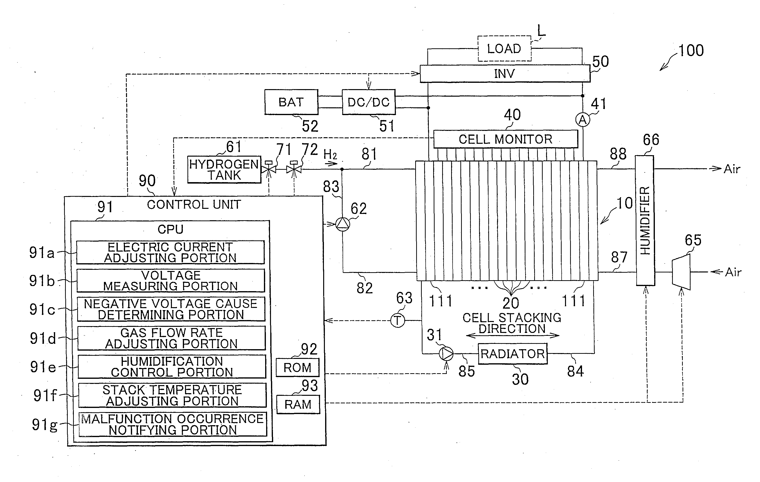
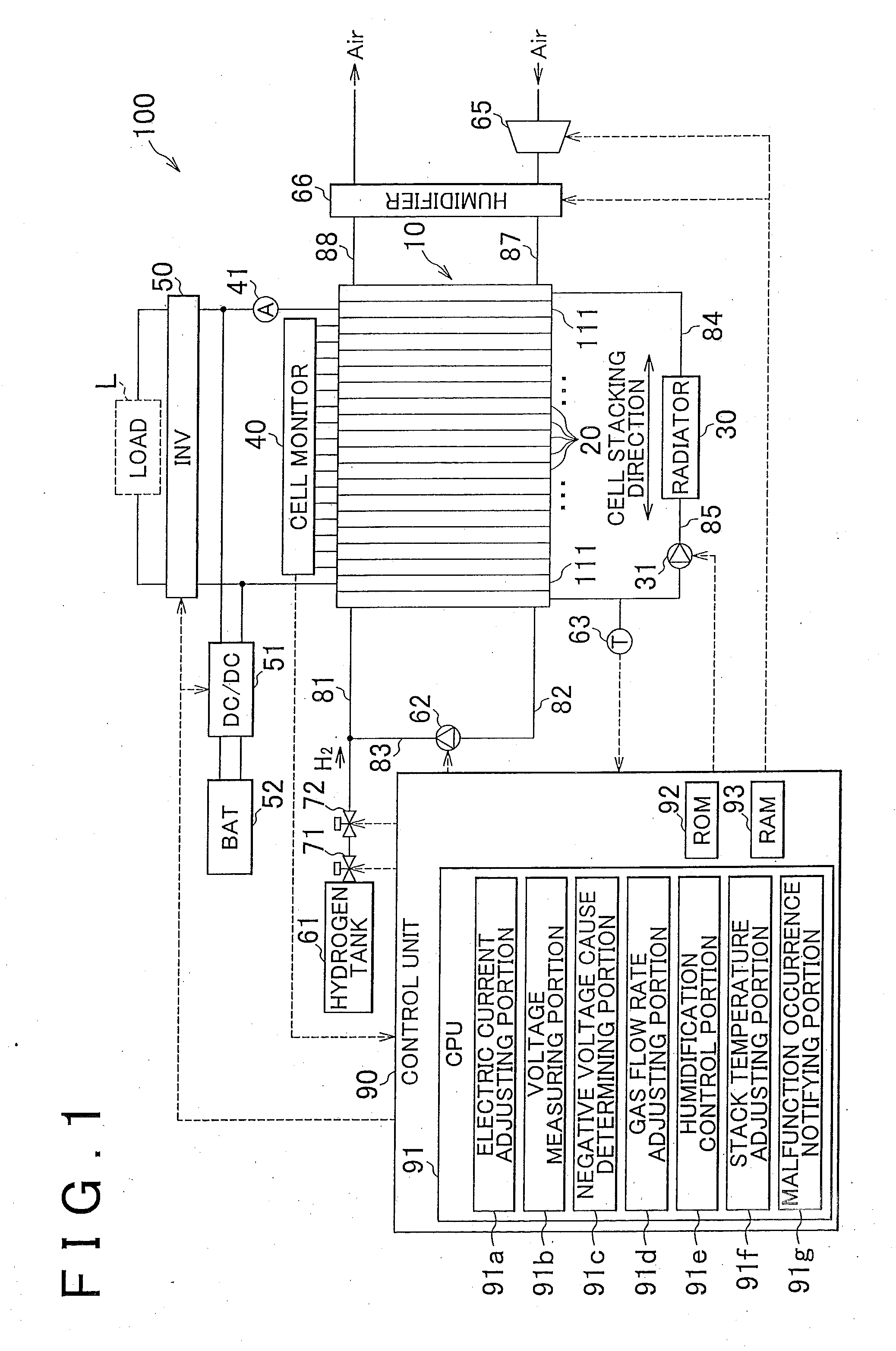
[0054]FIG. 1 is an explanatory diagram showing the schematic configuration of a fuel cell system according to an embodiment of the invention. In the embodiment, a fuel cell system 100 is provided in an electric vehicle and is used as a system that supplies power for driving the electric vehicle. The fuel cell system 100 includes a fuel cell stack 10, a hydrogen tank 61, a shutoff valve 71, a pressure adjusting valve 72, a first circulation pump 62, an air compressor 65, a humidifier 66, a radiator 30, a second circulation pump 31, a temperature sensor 63, a cell monitor 40, an electric current sensor 41, a DC-DC converter 51, a secondary battery 52, an inverter 50, a control unit 90, a fuel gas supply passage 81, a fuel gas discharge passage 82, a bypass passage 83, an oxidant gas supply passage 87, an oxidant gas discharge passage 88, a cooling medium supply passage 84; and a cooling medium discharge passage 85.

[0055]The fuel cell stack 10...

second embodiment

B. SECOND EMBODIMENT

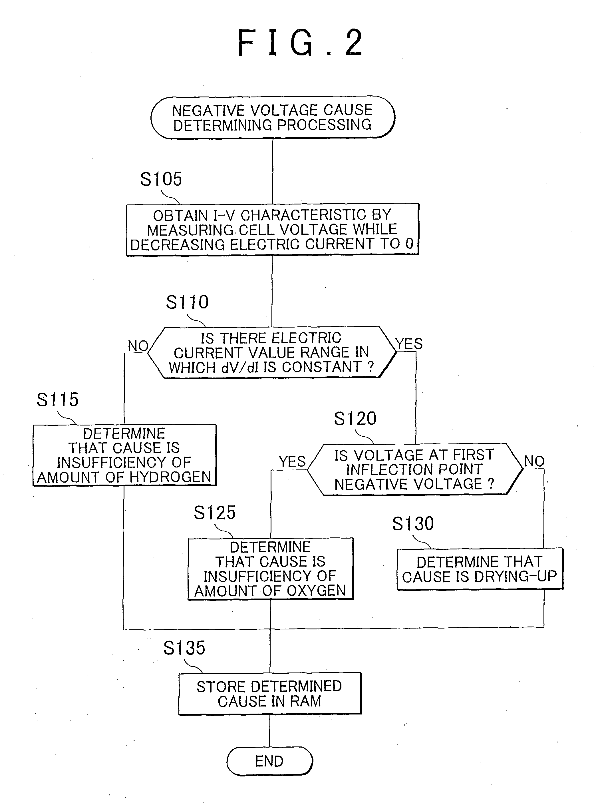
[0100]FIG. 9 is a flowchart showing steps of negative voltage cause determining processing in a second embodiment of the invention. A fuel cell system in the second embodiment is different from the fuel cell system 100 in the first embodiment in a method of determining the cause of the negative voltage. The other portions of the configuration of the fuel cell system in the second embodiment are the same as those of the configuration of the fuel cell system in the first embodiment. In the negative voltage cause determining processing in the first embodiment shown in FIG. 2, the cause of the negative voltage is determined by decreasing the electric current to 0, determining whether there is the electric current value range in which dV / dI is constant, and determining whether the voltage at the first inflection point is a negative voltage. In contrast, in the second embodiment, the value of the electric current is decreased in a predetermined electric current value r...

third embodiment

C. THIRD EMBODIMENT

[0113]FIG. 12 is a flowchart showing steps of negative voltage cause determining processing in a third embodiment. A fuel cell system in the third embodiment is different from the fuel cell system 100 in the first embodiment in that in the case where the cause of the negative voltage is the insufficiency of the amount of oxygen, it is determined whether the amount of oxygen is insufficient due to the blockage of the passage (i.e., the blockage of the oxidant gas supply passage 87) (in other words, no air is delivered to the cathode-side catalytic layer due to the blockage of the passage), or the amount of oxygen is insufficient in the vicinity of the catalytic layer (in other words, air is delivered to the cathode-side catalytic layer, but the amount of supplied air is smaller than the required amount), and in that a measure among different measures is taken according to the cause of the insufficiency of the amount of oxygen. The other portions of the configuratio...


PUM

PropertyMeasurementUnit
zero current-time voltageaaaaaaaaaa
open circuit voltageaaaaaaaaaa
voltageaaaaaaaaaa

Abstract

A fuel cell system includes a fuel cell; a voltage measuring portion that measures a voltage of the fuel cell; an electric current adjusting portion that adjusts an electric current flowing in the fuel cell; an electric current-voltage characteristic information obtaining portion that controls the electric current adjusting portion to change the electric current, and obtains electric current-voltage characteristic information that is information indicating a correspondence relation between an electric current value and a voltage value measured by the voltage measuring portion; and a negative voltage cause determining portion that determines, if the voltage of the fuel cell is a negative voltage, a cause of the negative voltage of the fuel cell, based on the obtained electric current-voltage characteristic information.

Description

BACKGROUND OF THE INVENTION[0001]1. Field of the Invention[0002]The invention relates to a fuel cell, and particularly to a decrease in a cell voltage.[0003]2. Description of Related Art[0004]A fuel cell including a Membrane-Electrode Assembly (MEA), in which catalytic electrode layers are provided on both sides of an electrolyte membrane, is used. In the fuel cell, electric power is generated by an electrochemical reaction caused using a fuel gas (for example, a hydrogen gas) and an oxidant gas (for example, air). It is known that in the fuel cell, the voltage of the fuel cell (i.e., a potential difference between a cathode and an anode: hereinafter, referred to as “cell voltage”) may decrease to a negative voltage due to the insufficiency of the amount of the fuel gas or the insufficiency of the amount of the oxidant gas. If the cell voltage becomes a negative voltage, for example, members (e.g., a platinum (Pt) catalyst and carbon) constituting a catalytic layer may deteriorate, ...

Claims


Application Information

Patent Timeline
Patent Type & Authority Applications(United States)
IPC IPC(8): H01M8/04G01R31/36
CPCH01M8/04358H01M8/04559H01M8/04589H01M8/04679H01M8/04731H01M8/04313H01M8/0485H01M8/04992Y02E60/50G01R31/3624H01M8/04126H01M8/04753H01M2008/1095G01R31/3842
Inventor KAWAHARA, SHUYAKATO, MANABUKUMEI, HIDEYUKI
Owner TOYOTA JIDOSHA KK
Why Eureka
Try Eureka