Vibrator source system for improved seismic imaging

a vibration source and seismic imaging technology, applied in the field of vibration source seismic source system, can solve the problems of erroneous estimates of subsurface geologic information, degrade source performance and imaging process, and unreliable computation of seismic reflection amplitude and phase information, so as to improve the design of the seismic vibratory source mechanism, improve the performance of the vibrator, and improve the processing of seismic data.

Inactive Publication Date: 2013-08-08
ROWSE SPENCER LEWIS +1
View PDF1 Cites 10 Cited by
  • Summary
  • Abstract
  • Description
  • Claims
  • Application Information

AI Technical Summary

Benefits of technology

[0007]A preferred embodiment of the invention provides an improved modeling method for a vibratory source system used for generation of seismic energy and utilized in a seismic data acquisition system such as are employed in the petroleum industry for the purpose of determining the subsurface geologic information related to the transmission and reflection of seismic waves. In the method of this system the model incorporates the vibrator mechanism (baseplate and reaction mass) and a small volume of earth beneath the baseplate of the vibrator (captured earth mass) as a damped mass spring system (harmonic oscillator). From classical mechanics the relationship between output and input of a harmonic oscillator undergoing forced vibration can be fully described if the natural frequency and damping of the harmonic oscillator are known as well as the character of the time varying input force. The accelerometers mounted on the baseplate and reaction mass respond to the total forces acting on the respective mass...

Problems solved by technology

Current practices are based on inadequate modeling of the seismic source system and resultant unreliable computation of seismic reflection amplitude and phase information.
The errors that result from the shortcomings of the source modeling degrade source performance and the imaging processes, and...

Method used


Image

  • Vibrator source system for improved seismic imaging
  • Vibrator source system for improved seismic imaging
  • Vibrator source system for improved seismic imaging

Examples


Embodiment Construction

Vibratory Seismic Source Theoretical Background

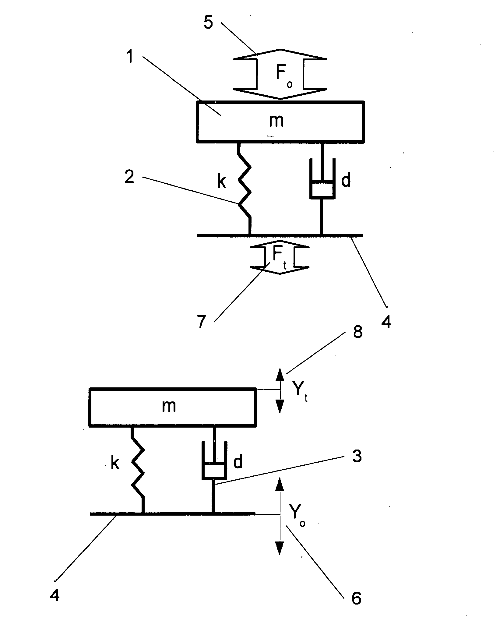
[0022]Current methods of generating seismic energy from a mechanical source at the earth's surface usually apply a time varying force to a rigid plate (baseplate) that is in contact with the ground. This applied force can be either a large amplitude force over a brief period of time (impulsive force) or by a small amplitude sinusoidal force over a relatively long period of time (vibratory force or sweep). The elastic earth and baseplate is usually represented by a mass-spring-damper system attached to a support as shown in FIG. 1 with the spring and damper elements representing an elastic volume of the earth beneath the baseplate. This simplistic system is considered a single degree of freedom (1DOF) system and, if the mass, spring and damping values are known, the response of this system (known as a harmonic oscillator) to a time varying force, (Fo), or displacement, (Yo), can be accurately determined.

[0023]For an impulsive excitation,...


PUM


Abstract

A system for modeling the output signal emanating from a seismic vibrator based on a superposed collection of damped harmonic oscillators, whose critical parameters are determined from signals from accelerometers on the baseplate and reaction mass portions of the vibrator together with the input force (pilot sweep). This modeled output signal is a more accurate representation of the seismic signal that propagates into the earth and may be used in the cross-correlation process to significantly enhance the accuracy of the recorded seismic data. Additionally, by modeling the output signal on a shot by shot basis, any changes in the ground's surface can be monitored and/or documented, and, if required, the sweep parameters can be varied shot by shot for optimum performance.

Description

CROSS-REFERENCE TO RELATED APPLICATION [0001]This application claims the priority date benefit of Provisional Application No. 61 / 631,867 filed Jan. 13, 2012.BACKGROUND OF THE INVENTION[0002]1. Field of the Invention[0003]The present invention relates to a novel vibrator source seismic source system incorporating the modeling of two fundamental oscillators and several higher-order oscillators which may be used to enhance the performance of the seismic source and to facilitate determination of an improved estimate of the down going seismic wave; these results may be further utilized to enhance the imaging of the subsurface geology.[0004]2. Description of the Related Art[0005]Those in the petroleum industry are increasingly concerned with improving the accuracy of seismic imaging based on reflected waves generated by seismic vibratory sources at or near the surface. Current practices are based on inadequate modeling of the seismic source system and resultant unreliable computation of ...

Claims


Application Information

Patent Timeline
IPC IPC(8): G01V1/28
CPCG01V1/28G01V1/0475
Inventor ROWSE, SPENCER LEWISTINKLE, ANTHONY
Owner ROWSE SPENCER LEWIS
Why Eureka
Try Eureka