Image based overlay measurement with finite gratings

a technology of image overlay and finite grating, applied in the field of overlay measurement, can solve the problems of reducing overlay alignment tolerances, difficult to measure the accuracy of one masking level to the previous level, and difficult to measure overlay accuracy to achieve the effect of improving the sensitivity of measured asymmetry

Active Publication Date: 2013-08-15
ONTO INNOVATION INC
View PDF6 Cites 110 Cited by
  • Summary
  • Abstract
  • Description
  • Claims
  • Application Information

AI Technical Summary

Benefits of technology

[0008]An image based overlay measurement is performed using an overlay target that includes shifted overlying grating patterns. Each grating consists of two or more lines, e.g., with the same width and constant pitch. The two gratings may have the same pitch or different pitches. If the midpoints of the gratings are coincident then the image of the overall pattern will be symmetric, while any offset from center alignment, whether produced deliberately or as a result of layer to layer overlay error, causes the overall pattern and hence its image to be asymmetric. The overlay target is configured so that a lateral separation between the nearest lines in gratings from different layers is sufficiently close to an image resolution limit of the image based metrology device, that proximity effects improve sensitivity of the measured asymmetry to overlay shift. The overlay target is imaged and an asymmetr...

Problems solved by technology

However, as the size of integrated circuit features continues to decrease, it becomes increasingly difficult to measure the overlay accuracy of one masking level to the previous level.
This overlay metrology problem becomes particularly difficult at submicrometer f...

Method used


Image

  • Image based overlay measurement with finite gratings
  • Image based overlay measurement with finite gratings
  • Image based overlay measurement with finite gratings

Examples


Embodiment Construction

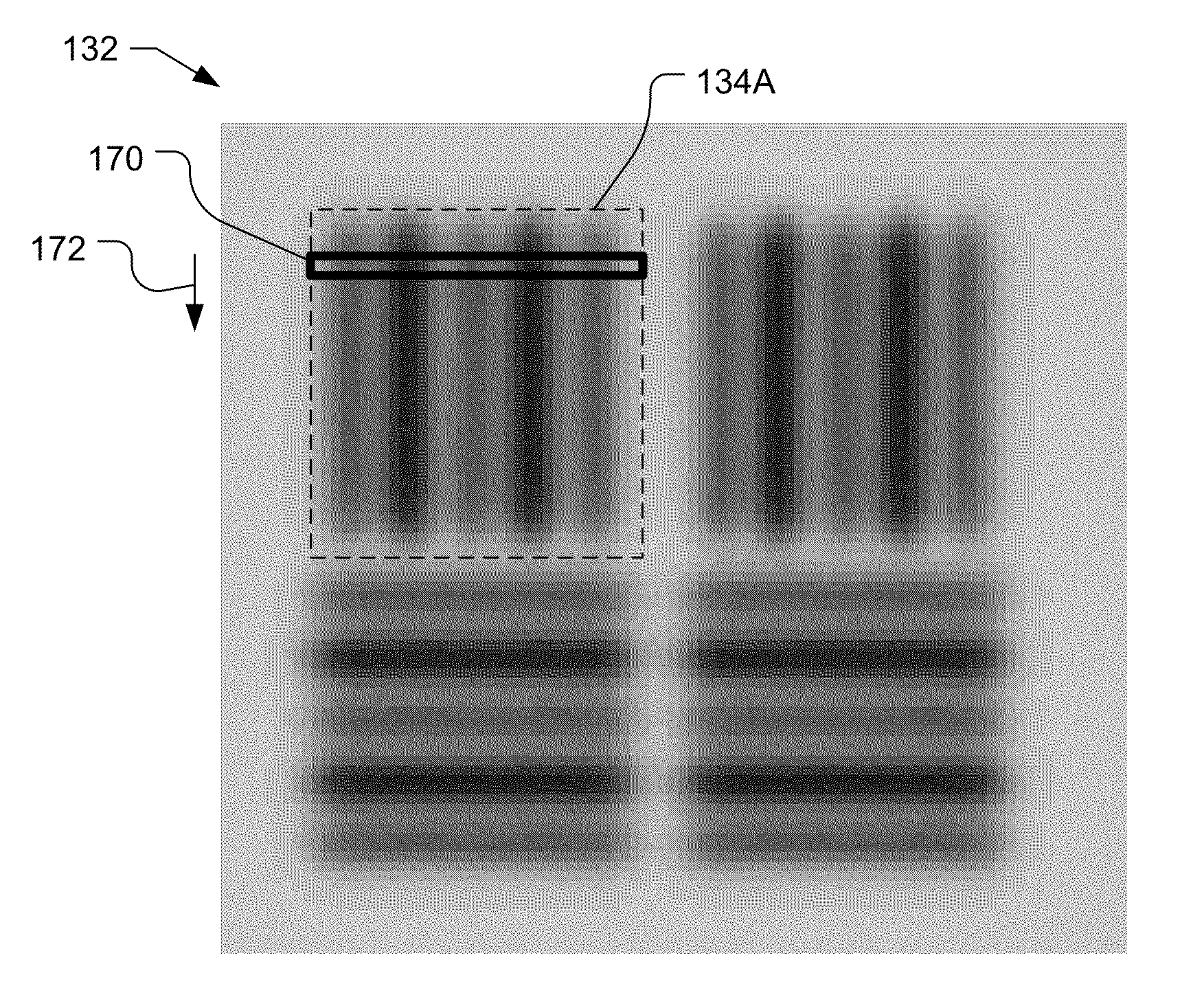
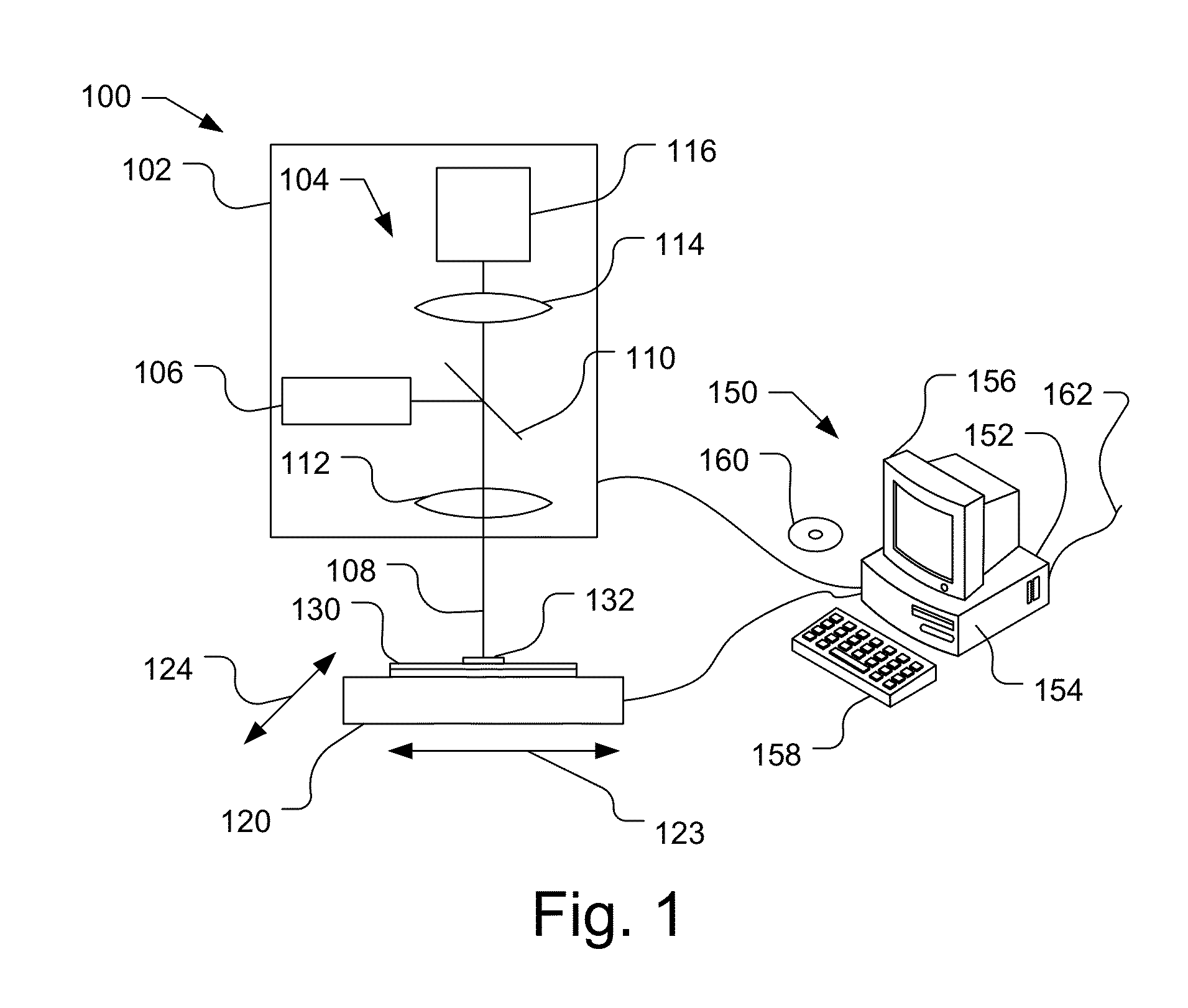
[0025]FIG. 1 shows a schematic view of an image based metrology device 100 that may be used to measure overlay errors on a sample 130 by imaging an overlay target 132 that includes shifted overlying gratings. Metrology device 100 includes an optical head 102 that is coupled to a computer 150, such as a workstation, a personal computer, central processing unit or other adequate computer system, or multiple systems. If desired, multiple optical heads, i.e., different metrology devices, may be combined in the same metrology device 100. The computer 150 may control the movement of a stage 120 that holds the sample 130 and / or the optical head 102. The stage 120 may be capable of horizontal motion in either Cartesian (i.e., X and Y) coordinates, as indicated by arrows 123 and 124, or Polar (i.e., R and θ) coordinates or some combination of the two. The stage may also be capable of vertical motion.

[0026]The optical head 102 includes an imaging system 104 that includes an infra-red, visible...


PUM


Abstract

An image based overlay measurement is performed using an overlay target that includes shifted overlying gratings. The overlay target is imaged and an asymmetry is measured in the image of the overlaid gratings. The asymmetry is used to determine the overlay error. For each measurement direction, the overlay target may include two or more overlay measurement pads with different offsets between the top and bottom gratings. The measured asymmetries and offsets in the overlay measurement pads may be used to determine the overlay error, e.g., using self-calibration. The pitch and critical dimensions of the overlay target may be optimized to produce a greatest change of symmetry with overlay error for a numerical aperture and wavelength of light used by the image based metrology device.

Description

CLAIM OF PRIORITY UNDER 35 U.S.C. §119[0001]This application claims under 35 USC §119 the benefit of and priority to U.S. Provisional Application No. 61 / 599,333, filed Feb. 15, 2012, which is incorporated by reference herein in its entirety.BACKGROUND[0002]1. Background Field[0003]Embodiments of the subject matter described herein are related generally to overlay measurement, and more particularly to image based overlay measurement.[0004]2. Relevant Background[0005]Semiconductor processing for forming integrated circuits requires a series of processing steps. These processing steps include the deposition and patterning of material layers such as insulating layers, polysilicon layers, and metal layers. The material layers are typically patterned using a photoresist layer that is patterned over the material layer using a photomask or reticle. Typically, the photomask has alignment targets or keys that are aligned to fiduciary marks formed in the previous layer on the substrate. Howeve...

Claims


Application Information

Patent Timeline
IPC IPC(8): G01B11/26
CPCG01B11/26G03F7/70633
Inventor SMITH, NIGEL P.
Owner ONTO INNOVATION INC
Why Eureka
Try Eureka