Mirror driving device and method of controlling the device

Active Publication Date: 2013-08-15
FUJIFILM CORP
View PDF3 Cites 30 Cited by
  • Summary
  • Abstract
  • Description
  • Claims
  • Application Information

AI Technical Summary

Benefits of technology

[0029]According to the presently disclosed subject matter, the mirror part can be tilted with a large deflection angle with the use of a combination of a plurality of piezoelectric cantilevers. Also, if a material with excellent piezoelectric characteristics, such as Nb-doped PZT with a high piezoelectric constant, is used, a large deflection angle can be obtained with a relatively small number of times of folding, and therefore the resonance frequency can be designed to be high. With this, a quick response can be made, and influences due to disturbance vibr

Problems solved by technology

[2] If the deflection angle is increased by, for example, folding the piezoelectric cantilever, the resonance frequ

Method used


Image

  • Mirror driving device and method of controlling the device
  • Mirror driving device and method of controlling the device
  • Mirror driving device and method of controlling the device

Examples


first embodiment

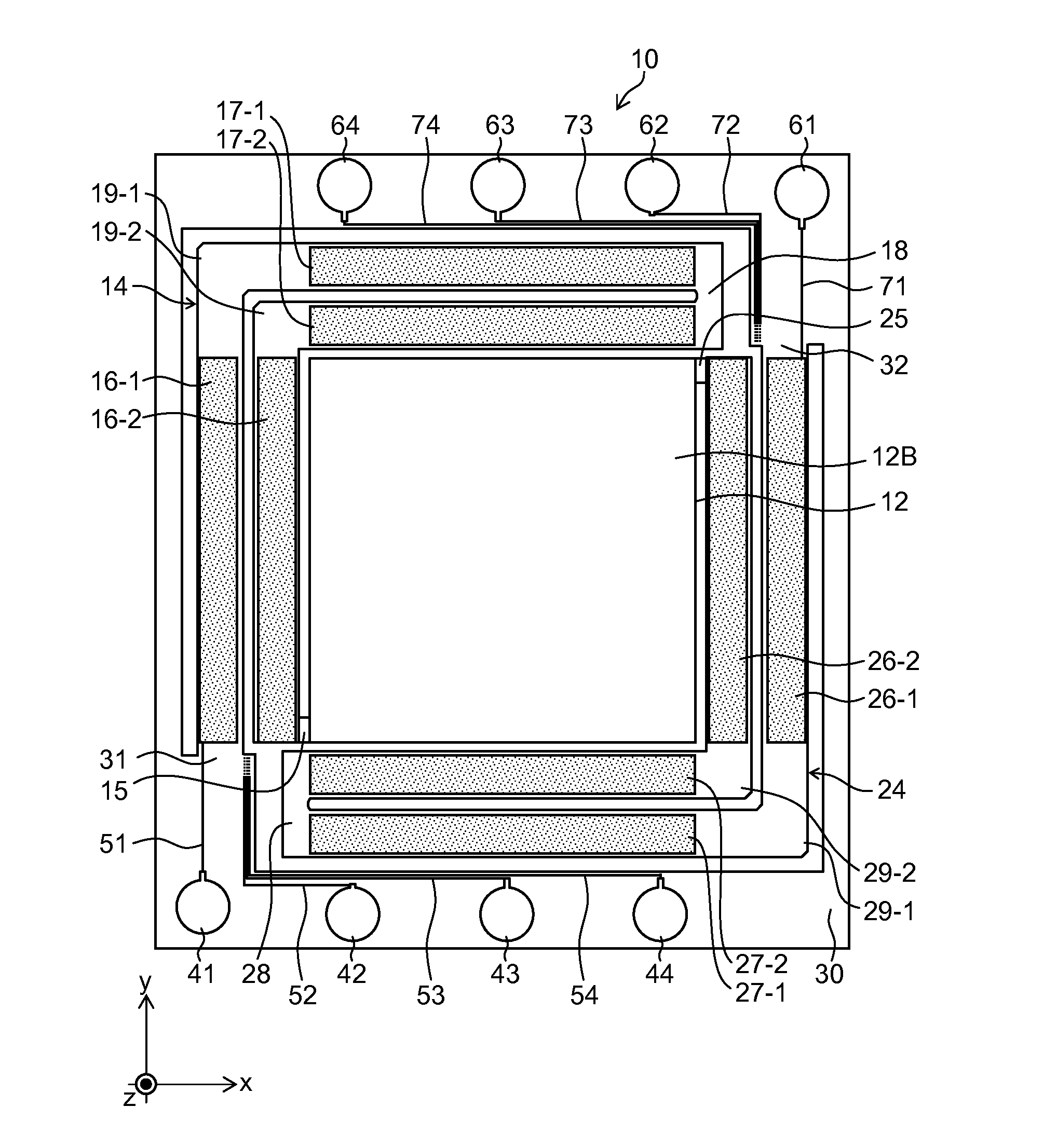
[0057]FIG. 1 is a plan view of a MEMS scanner device according to a first embodiment.

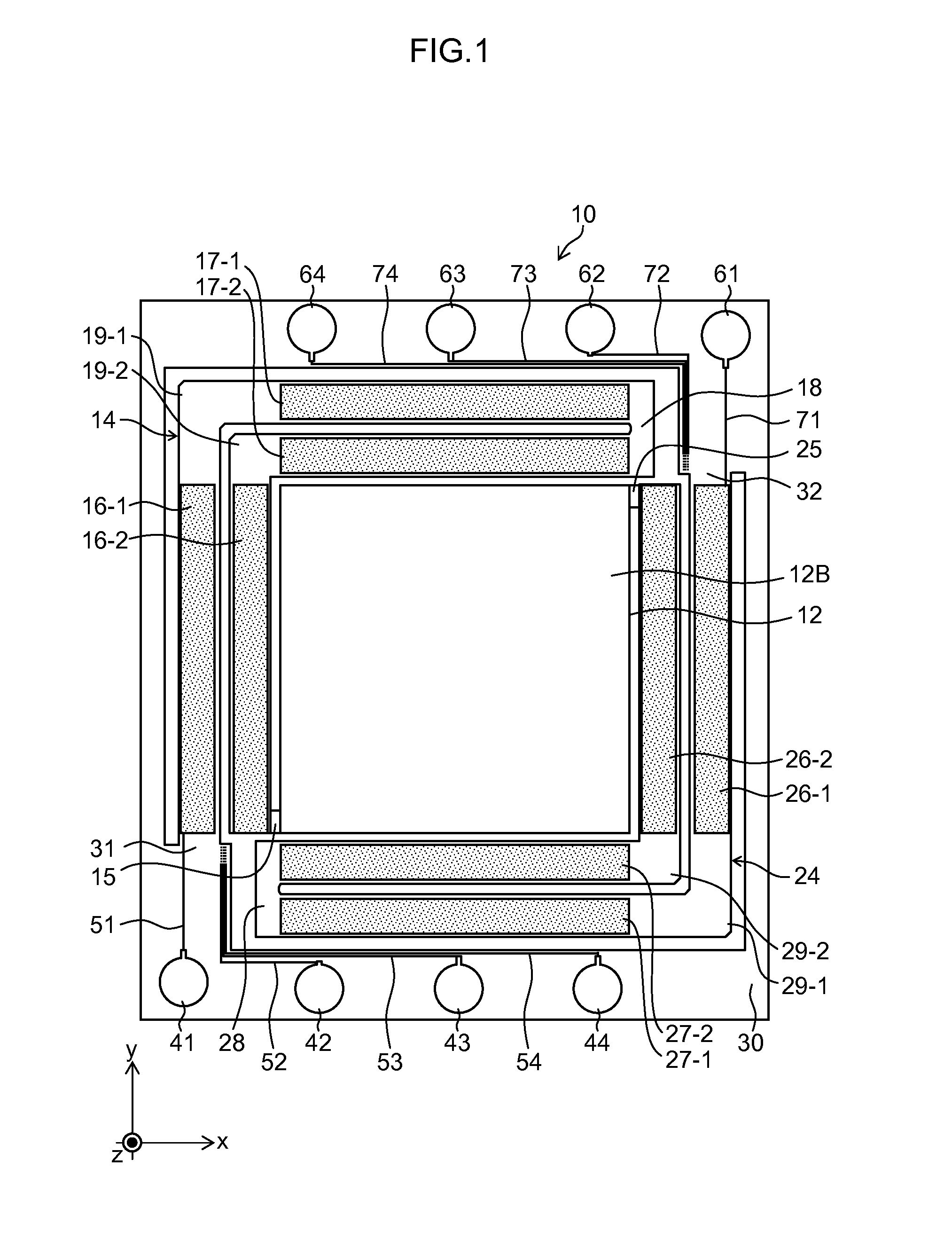
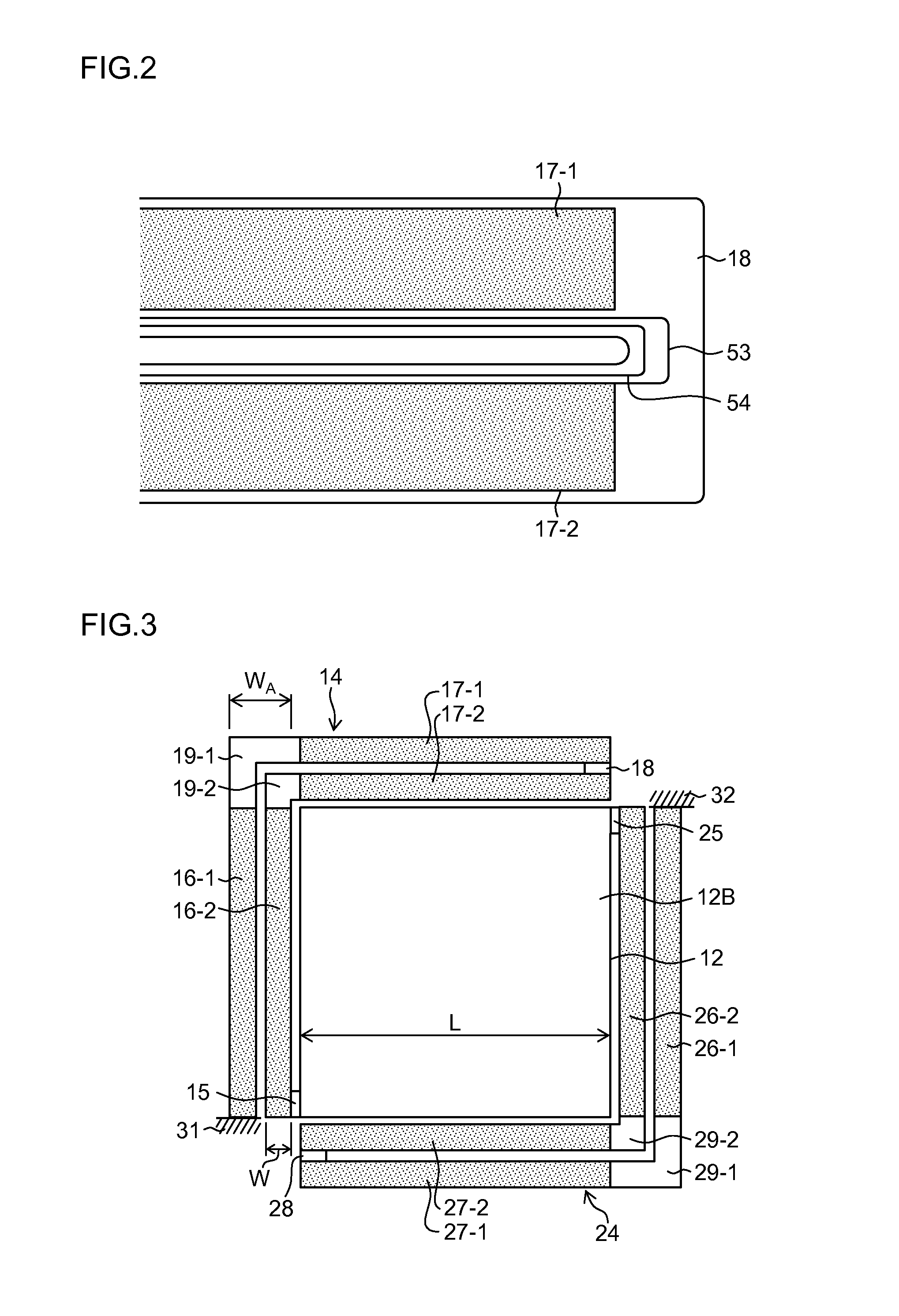
[0058]FIG. 2 is a partially enlarge view of FIG. 1. FIG. 3 is a drawing schematically depicting a device structure of FIG. 1. As depicted in these drawings, a MEMS scanner device 10 (corresponding to a “mirror driving device”) according to the present embodiment includes a mirror part 12, two actuators 14 and 24 so as to surround this mirror part 12, and a fixing frame 30 supporting these actuators 14 and 24. At diagonal positions of the mirror part 12, mirror support parts 15 and 25 are formed. The actuators 14 and 24 have one end connected to the mirror support parts 15 and 25 and the other end fixed to fixing parts denoted by reference numerals 31 and 32, respectively.

[0059]The mirror part 12 in this example has a substantially rectangular shape in a planar view. On a mirror surface serving as a reflection surface 12B for reflecting light (an upper surface of the mirror part 12), a metal thin fil...

example 1

Example of Method of Manufacturing MEMS Scanner Device

[0129]As Example 1, the MEMS scanner device 10 was fabricated through the following procedure.

[0130](Process 1)

[0131]On a SOI (Silicon On Insulator) substrate having a handle layer of 350 μm, a box layer of 1 μm, and a device layer of 10 μm, a Ti layer of 30 nm and an Ir electrode layer of 150 nm were formed by sputtering at a substrate temperature of 350 degrees Celsius. These Ti layer and Ir electrode layer correspond to the lower electrode 83 in FIG. 4.

[0132](Process 2)

[0133]On the obtained substrate described above, a film of a PZT layer of 2 μm was formed by using a radio frequency (RF) sputtering device. As a film forming gas, a mixed gas of 97.5% Ar and 2.5% O2 was used, and a target material with a composition of Pb 1.3 ((Zr 0.52 Ti 0.48) 0.88 Nb 0.12) O3 was used. The film forming pressure was 2.2 m Torr, and the film formation temperature was 450 degrees Celsius.

[0134](Process 3)

[0135]The substrate obtained above was pr...

modification example 1

[0138]While one actuator includes four cantilevers in the first embodiment, the number of cantilevers included in one actuator is not restricted to the number in this example, and may be further increased. However, if the number of cantilevers is increased, the resonance frequency is increased, and the device tends to become vulnerable to disturbance. Therefore, it is required to select the number of cantilevers for combination according to design requirements (according to the design of the resonance frequency in consideration of the use environment). Also, in view of cancelling of bending displacements in the same direction (cancelling of displacements in the same direction due to initial flexure caused by residual stress and DC offset), which will be described further below, it is required to fold and connect a plurality of piezoelectric cantilevers so that the fixing part of each actuator and the mirror support part are close to each other.

[0139](Regarding Cancelling of Bending ...


PUM


Abstract

A mirror driving device can include: a mirror part having a reflection surface configured to reflect light; mirror support parts formed at portions of the mirror part diagonal to each other; and a first actuator and a second actuator placed so as to surround the mirror part, wherein the first actuator and the second actuator each have a structure in which a plurality of first piezoelectric cantilevers with a longitudinal direction oriented to a direction of a first axis and a plurality of second piezoelectric cantilevers with a longitudinal direction oriented to a second axis are coupled together so as to be folded, and each of the first actuator and the second actuator has one end connected to the mirror part via a relevant one of the mirror support parts and another end connected to a fixing part near the mirror support part to which the one end is coupled.

Description

BACKGROUND OF THE INVENTION[0001]1. Field of the Invention[0002]The presently disclosed subject matter relates to a mirror driving device and method of controlling the device and, in particular, relates to the structure of a micromirror device suitable for an optical deflector for use in optical scanning and others and technologies for controlling the driving of the micromirror device.[0003]2. Description of the Related Art[0004]A microscanner (hereinafter referred to as a “MEMS (Micro Electro Mechanical System) scanner fabricated by using silicon (Si) microfabrication processing) has a feature of being small in size and having low power consumption compared with a polygon mirror, which is a conventional optical scanning module, or others. For this reason, the MEMS scanner is expected be widely applied from a laser projector to an optical diagnostic scanner such as an Optical Coherence Tomography (OCT).[0005]Among various schemes for driving the MEMS scanner, a piezoelectric driving...

Claims


Application Information

Patent Timeline
IPC IPC(8): G02B26/10
CPCG02B26/10H01L41/0953G02B26/0858H10N30/2044
Inventor NAONO, TAKAYUKI
Owner FUJIFILM CORP
Why Eureka
Try Eureka