High-Efficiency Internal Combustion Engine and Method for Operating Employing Full-Time Low-Temperature Partially-Premixed Compression Ignition with Low Emissions

a technology of internal combustion engine and compression ignition, which is applied in the direction of machines/engines, output power, electric control, etc., can solve the problems of increasing the ignition delay period, unable to achieve classic si preignition, and unable to achieve classic combustion knock, etc., to achieve the effect of high efficiency of conventional diesel engines, longer ignition delay and higher volatility

Inactive Publication Date: 2013-08-22
DELPHI TECH IP LTD
View PDF12 Cites 53 Cited by
  • Summary
  • Abstract
  • Description
  • Claims
  • Application Information

AI Technical Summary

Benefits of technology

[0004]Gasoline Direct Injection Compression Ignition (GDCI) is a new combustion system that overcomes many of the fundamental limitations of other gasoline engines. GDCI provides the high efficiency of conventional diesel engines with unleaded regular gasoline. Compared to diesel fuel, gasoline has much higher volatility and longer ignition delay, which are key enablers to a partially premixed compression ignition combustion process. An important outcome is that gasoline can be injected late on the compression stroke at GDi-like fuel pressure (100 to 500 bar) to achieve a sufficiently premixed charge.

Problems solved by technology

Because of late injection, no endgas exists, and classic combustion knock is not possible.
Classic SI preignition is also not possible.
Cooled exhaust gas recirculation (EGR) dilutes the mixture, increases the ignition delay period, and slows heat release rates for low combustion noise.

Method used


Image

  • High-Efficiency Internal Combustion Engine and Method for Operating Employing Full-Time Low-Temperature Partially-Premixed Compression Ignition with Low Emissions
  • High-Efficiency Internal Combustion Engine and Method for Operating Employing Full-Time Low-Temperature Partially-Premixed Compression Ignition with Low Emissions
  • High-Efficiency Internal Combustion Engine and Method for Operating Employing Full-Time Low-Temperature Partially-Premixed Compression Ignition with Low Emissions

Examples


Embodiment Construction

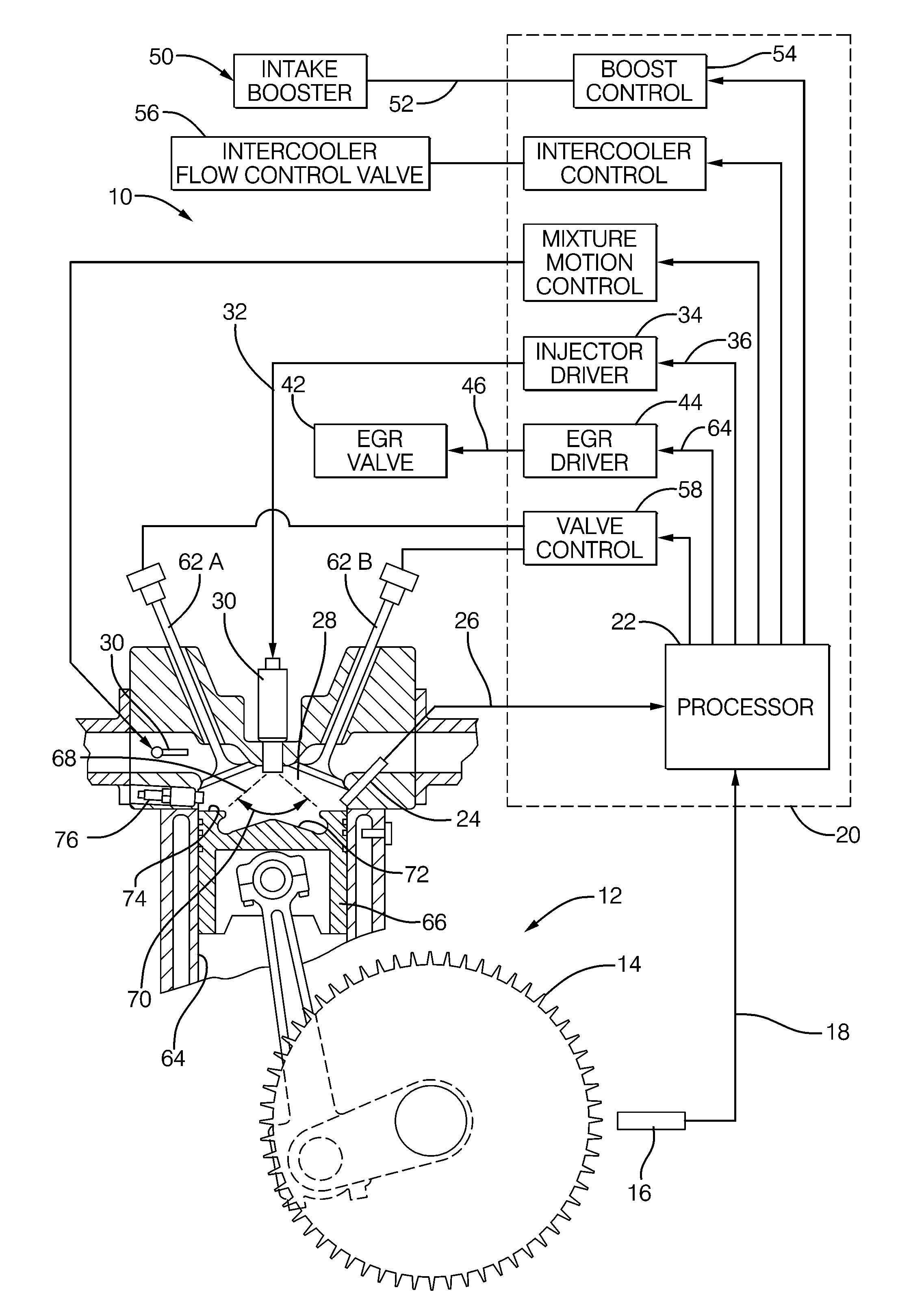
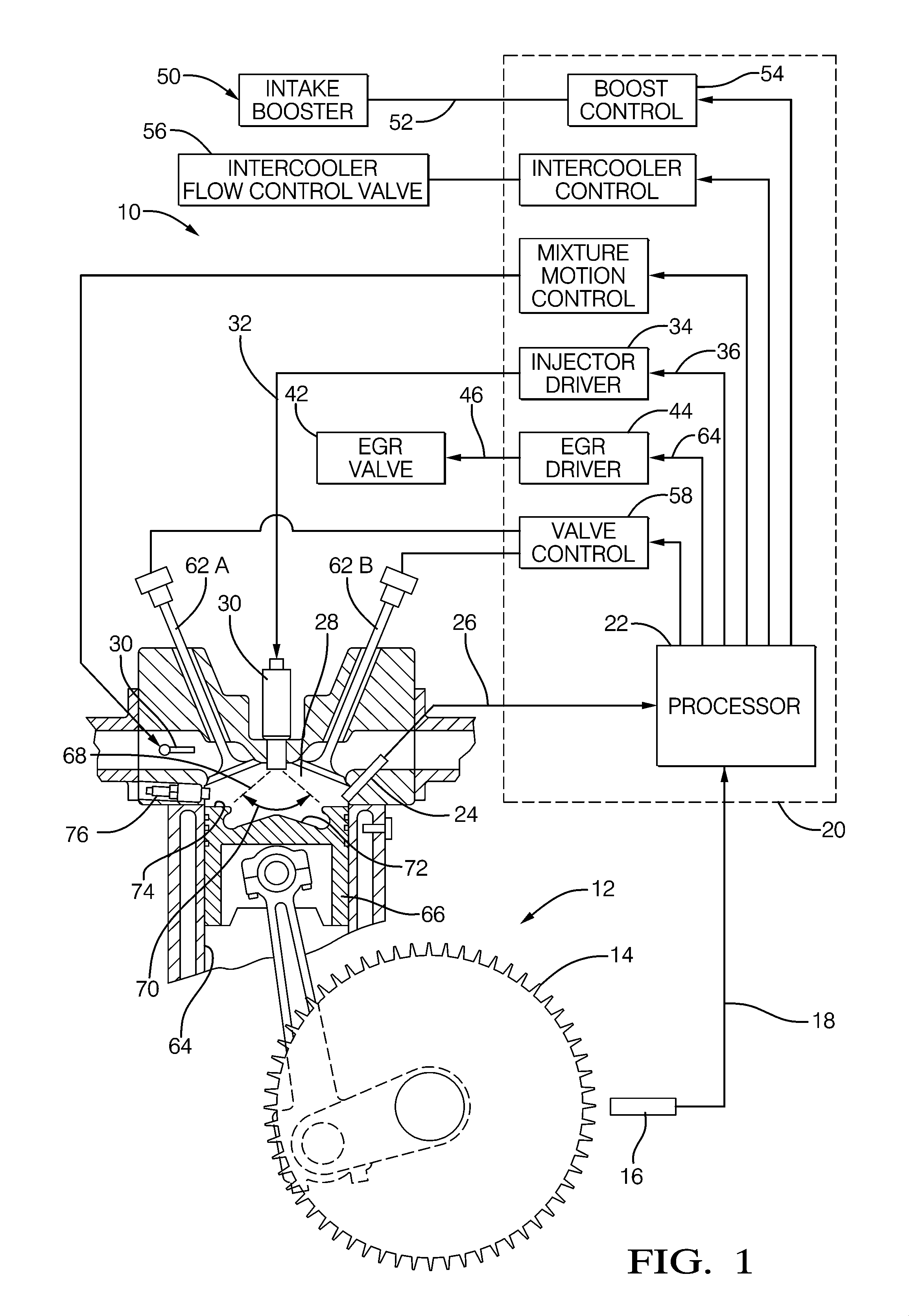
[0015]In accordance with an embodiment of an engine control system, FIG. 1 illustrates an engine control system 10 for controlling an internal combustion engine 12 operating at an engine operating condition. The engine 12 is illustrated as having a single cylinder bore 64 containing a piston 66, wherein the region above the piston 66 defines a combustion chamber 28; however it will be appreciated that the system 10 may be adapted to engines having multiple cylinders and combustion chambers. The engine control system 10 may control an engine having multiple combustion chambers by individually controlling each of the multiple combustion chambers, or may control such an engine based on a signal from a sensor that is representative of a typical or average condition in each combustion chamber. The system 10 may include a toothed crank wheel 14 and a crank sensor 16 positioned proximate to the crank wheel 14 such that the crank sensor 16 is able to sense rotational movement of the crank w...


PUM


Abstract

An engine system and a method of controlling a combustion process in an internal combustion engine are disclosed. The combustion process is based on compression ignition of a stratified air-fuel mixture using a high octane fuel such as gasoline. Multiple fuel injections may be used in a given combustion cycle. Fuel injection timing, EGR, exhaust rebreathing, late intake valve closing, and intake boost are controlled to enable autoignition over essentially the entire speed and load operating range of the engine, while providing reduced emissions, low noise, and low fuel consumption.

Description

CROSS-REFERENCES TO RELATED APPLICATIONS[0001]This application is a national stage application under 35 U.S.C. 371 of PCT Application No. PCT / US2011 / 057842 having an international filing date of 26 Oct. 2011, which designated the United States, which PCT application claimed the benefit of U.S. Provisional Patent Application No. 61 / 406,689 filed 26 Oct. 2010, the entire disclosure of each of which are hereby incorporated herein by reference.STATEMENT REGARDING FEDERALLY SPONSORED RESEARCH OR DEVELOPMENT[0002]This invention was made with government support under Contract No. DE-EE0003258 awarded by the Department of Energy. The government has certain rights in the invention.BACKGROUND[0003]Near-term regulations (Tier2 Bin 5 / Bin 2 and Euro 6) for CAFE, CO2 emissions and regulated emissions including NOx, CO, HC, and particulate matter (PM) are demanding advanced internal combustion (IC) engines with greatly improved combustion processes. While diesel engines are already very efficient,...

Claims


Application Information

Patent Timeline
Patent Type & Authority Applications(United States)
IPC IPC(8): F02M25/07
CPCF02B1/12F02M25/07F02B23/101F02B29/0437F02B29/0493F02B2023/102F02D13/0207F02D13/0265F02D13/0269F02D13/0273F02D41/0002F02D41/006F02D41/008F02D41/3017F02D41/401F02D41/402F02D2041/001F02D2041/3052F02M25/0752Y02T10/125Y02T10/44Y02T10/142Y02T10/42F02B17/005F02M26/01Y02T10/12Y02T10/40
Inventor SELLNAU, MARK C.HOYER, KEVIN S.SINNAMON, JAMES F.
Owner DELPHI TECH IP LTD
Why Eureka
Try Eureka