Fluid shockwave reactor

a reactor and shock wave technology, applied in the field of energy converters, can solve the problems of high energy consumption in industrial production, strict requirements on equipment structure and equipment performance, and high requirements on fluid particle size, so as to improve the treatment effect and improve the efficiency of conversion

Active Publication Date: 2013-08-29
QINZHOU AURASOURCE TECH
View PDF5 Cites 19 Cited by
  • Summary
  • Abstract
  • Description
  • Claims
  • Application Information

AI Technical Summary

Benefits of technology

[0009]Beneficial effects of the fluid shockwave reactor are as follows: The fluid shockwave reactor according to the present invention, focused on flowing characteristics of fluid, takes the optical resonator principle as reference and is designed a chamber structure of the fluid shockwaves. This resonant chamber structure can gather the shockwave energy produced by strong turbulence when opposite jets collide, through reflection and aggregation caused by confocal reflection chamber with different radius of curvature and intervals or caused by reflective chamber with concentric spherical concave. The turbulen

Problems solved by technology

The dependence on an ultra high pressure leads to high energy consumptions in industrial productions, strict requirements on the equipment structure and equipment performance, high requirements on the particle size of fluid materials, and low levels of safety in industrial productions.
The main pr

Method used


Image

  • Fluid shockwave reactor
  • Fluid shockwave reactor
  • Fluid shockwave reactor

Examples


example 1

[0030

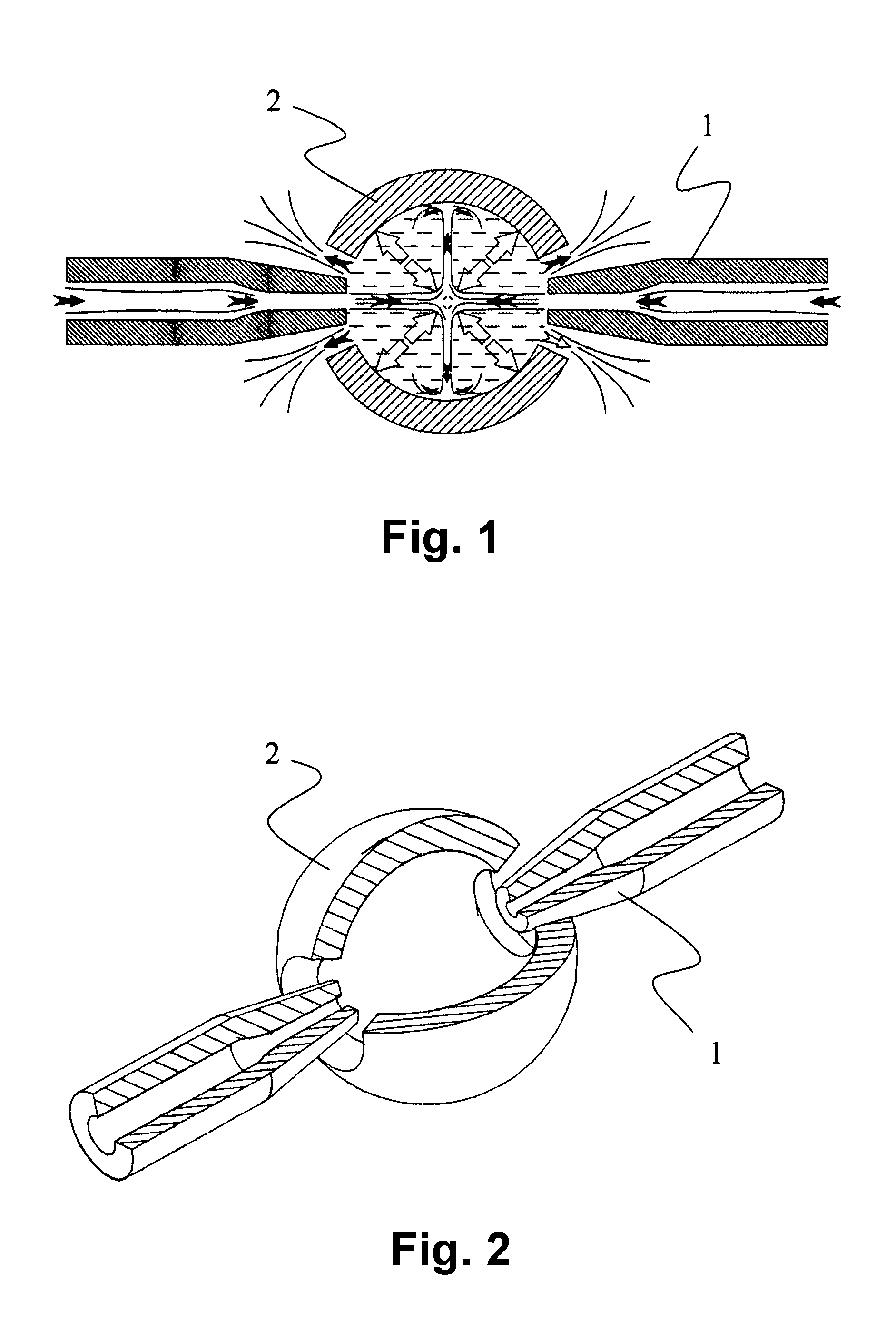
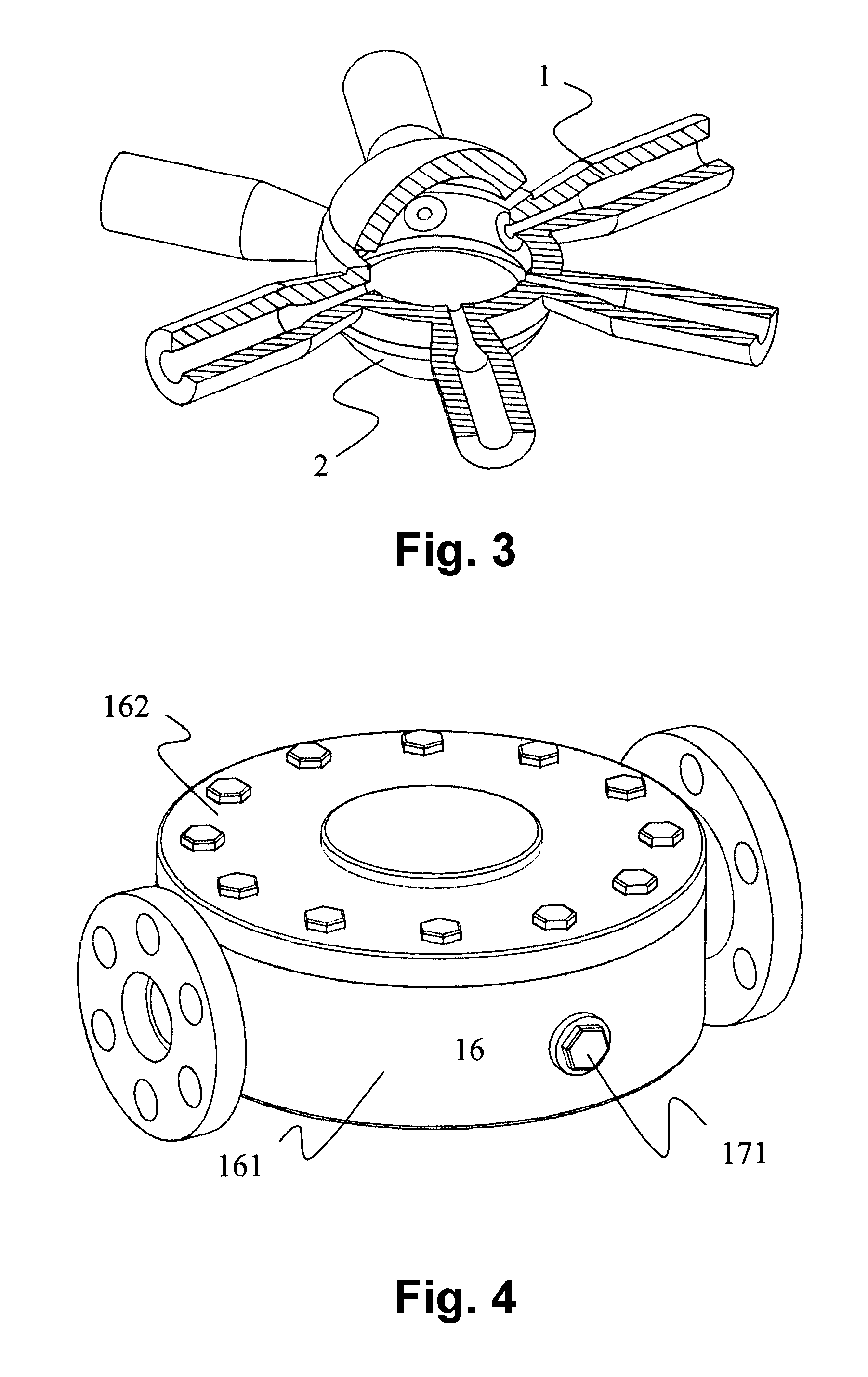
Shockwave Reactor With a Single Set of Collision Jet

[0031]The outer shell of the fluid shockwave reactor device is made of metal materials or high-polymer synthetic materials having a high strength; the nozzles and reflection energy convergence cover are made of a metal material having a high hardness, a ceramic material having a high strength or a metal-ceramic composite material.

[0032]1. Feeding channel 11;

[0033]2. Spherical resonance chamber 12, which is a hollow chamber formed by a rigid ballconcave surface, the spherical resonance chamber 12 of this example is surrounded by two hollow half-spheres 121, which are reflection energy convergence covers. The spherical resonance chamber can also be made into an integral structure in accordance with practical demands;

[0034]3. Discharge port 13, located at the two sides of the reflection energy convergence cover are a jet port and a discharge port, they are located in the same place, herein referred to as discharge port.

[0035]4. N...

example 2

[0043

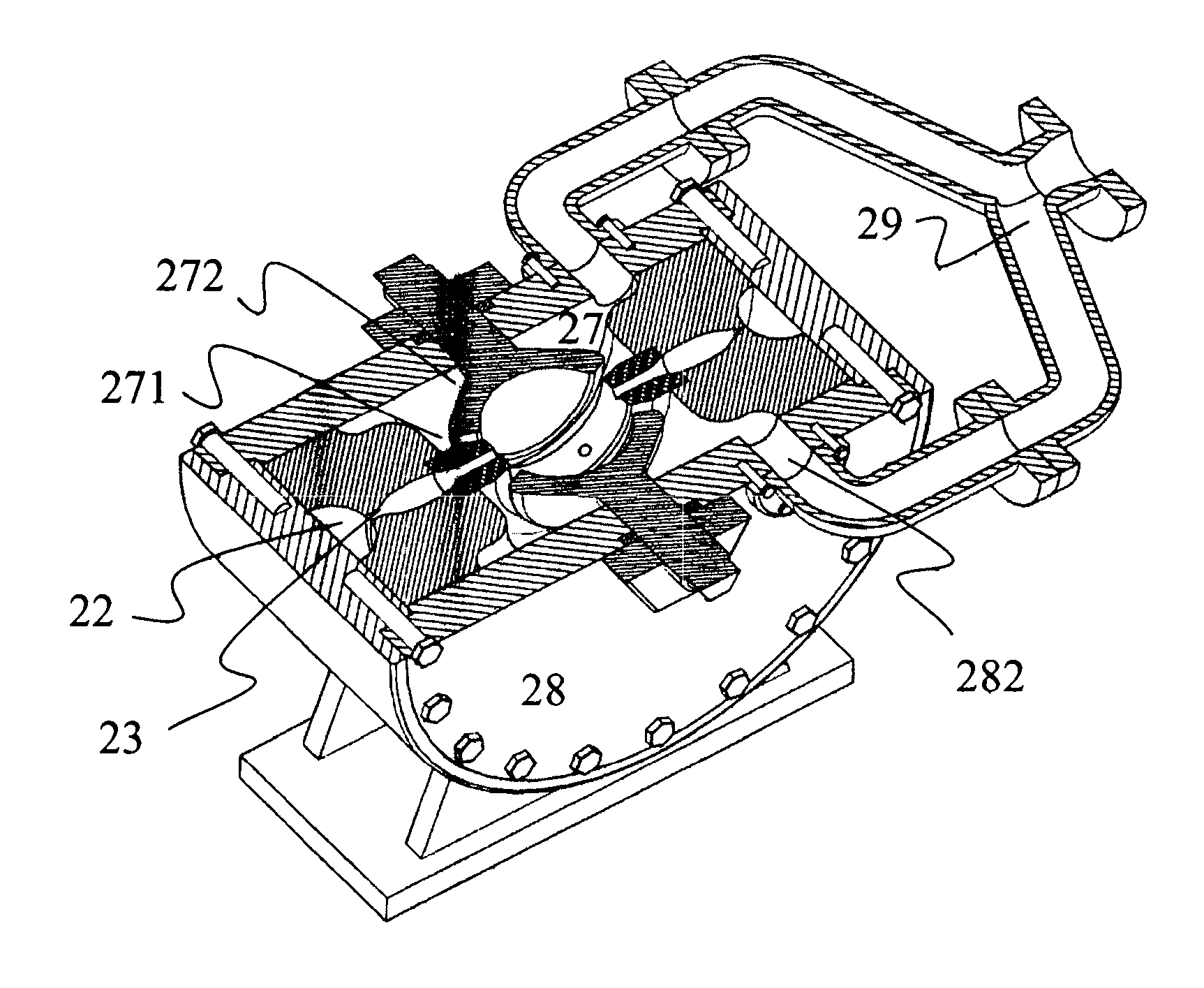
Shockwave Reactor With Multiple Sets of Collision Jets

[0044]As shown in FIGS. 9-13, the shockwave reactor with multi-sets collision jets is consists of:

[0045]1. Feeding channel and outer shell 21, as shown in FIG. 9, which are composed by a shell 211, a feeding pipe 212, a flang 213 and a support 214. The feeding channel is communicated with the vortex-type feeding chamber in a tangential direction, its cross-sectional area is much larger than the total cross-sectional areas of all the nozzles;

[0046]2. Vortex-type feeding chamber 22, as shown FIGS. 10, 12, and 13, which is located inside the shell, and has a circular shape;

[0047]3. Slotted self-servo diversion chamber 23, as shown in figures 10, 12, and 13, which is located inside the vortex-type feeding chamber 22. The inner wall of the chamber is formed by symmetrical revolving curves. The slot spacing is less than the minimum diameter sizes of the acceleration channel 242 and the nozzles 243;

[0048]4. High pressure sealed noz...


PUM


Abstract

The present invention relates to a fluid shockwave reactor. The fluid shockwave reactor introduces laser resonance theory into the field of fluid physics. It consists of a shockwave resonance energy concentration device and at least one set of jet collision device. The shockwave resonance energy concentration device can enhance the shockwave strength produced during jet collisions; strengthen the ultrahigh pressure and cavitation effect of the shockwave field; it can also intensify physical and chemical effects on the processed materials. The fluid shockwave reactor can achieve ultrafine crushing on the fluid materials with lower energy consumption. Under certain technological conditions, the fluid shockwave reactor may also effectively catalytize the chemical reaction process on fluid materials.

Description

FIELD OF THE INVENTION[0001]The present invention relates to an energy converter that makes use of a jet to generate shockwaves, especially to a fluid shockwave reactor that carries out an ultrafine crush treatment for fluid materials, or realizes catalytic treatment for chemical reactions of liquid materials.BACKGROUND OF THE INVENTION[0002]In the field of modern industrial production, mechanical equipments for carrying out an ultrafine crush treatment for fluid materials have been widely used, such as high pressure jet collision pulverizers, high pressure target jet pulverizers, high pressure homogenizers, etc. At present, in order to achieve ultrafine crushing effect of fluid materials, this type of equipment needs working pressure as high as 100-200 MPa or even higher. The dependence on an ultra high pressure leads to high energy consumptions in industrial productions, strict requirements on the equipment structure and equipment performance, high requirements on the particle siz...

Claims


Application Information

Patent Timeline
IPC IPC(8): B01J19/26
CPCB01F5/0256B01J4/002B01J19/2405B01J19/26B01J2219/1942B01J3/08C01P2004/62B01J2219/00164C01G25/02C01G39/06C09C3/043C09C1/00C09C1/0003B01J2219/00162B01F25/23B02C19/06B02C19/065B02C19/063
Inventor ZHANG, XIAODINGZHANG, CHUANZHONG
Owner QINZHOU AURASOURCE TECH
Why Eureka
Try Eureka