

Light source unit and projection display device with the same
a technology of projection display device and light source unit, which is applied in the direction of non-linear optics, lighting and heating apparatus, instruments, etc., can solve the problems of only about half of the total amount of light, the light leakage through the side surface is large, and the optical system cannot be efficiently coupled to the projector, so as to reduce the size of the gap, reduce the intensity of outgoing light, and reduce the effect of heat resistan
- Summary
- Abstract
- Description
- Claims
- Application Information
AI Technical Summary
Benefits of technology
Problems solved by technology
Method used
Image

Examples
first exemplary embodiment
[0090]FIG. 6 is a perspective view showing a configuration of a light source unit according a first exemplary embodiment. FIG. 7 is a cross-sectional view of the light source unit shown in FIG. 6.
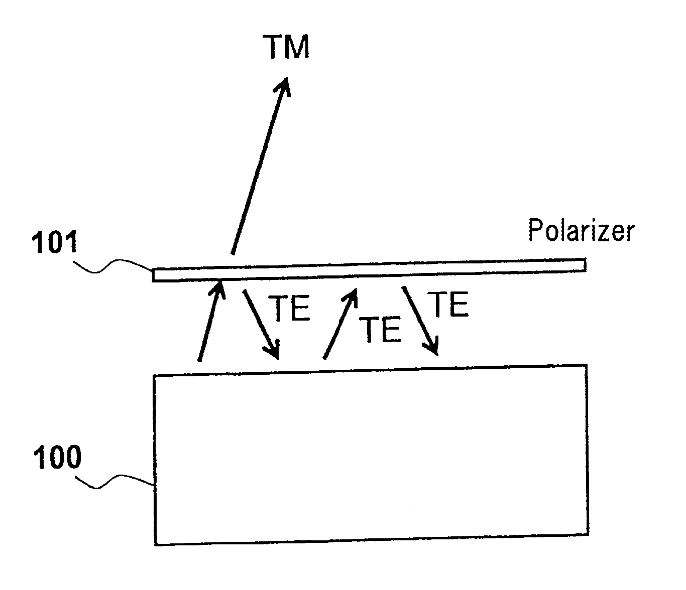
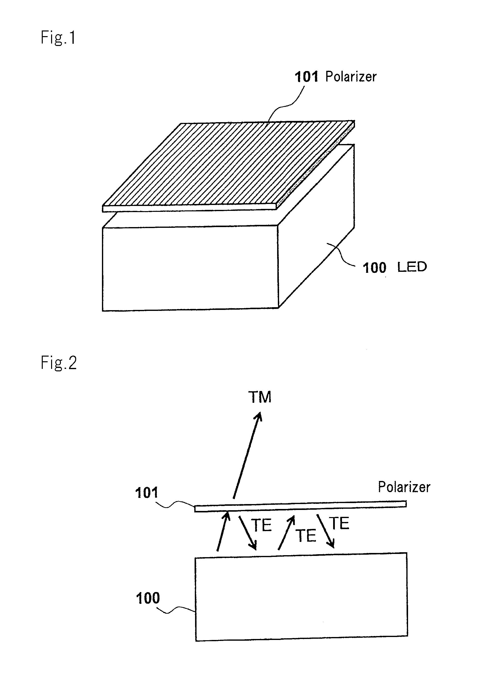
[0091]As shown in FIG. 6 and FIG. 7, the light source unit includes LED 1 with emission surface 1a and polarizer 2 provided opposite emission surface 1a.
[0092]LED 1 includes a stacking section in which, for example, an n-type layer and a p-type layer are deposited such that they sandwich an active layer. An n-type layer-side surface or a p-type layer-side surface of the stacking section corresponds to emission surface 1a. Light generated by the active layer is emitted through emission surface 1a. LED 1 may be a surface-emitting solid light source such as a semiconductor laser.
[0093]Light traveling from polarizer 2 side into LED 1 is specularly reflected by emission surface 1a of LED 1 or inside LED 1. The polarization state of the light present before the specular reflection is maintained ...
second exemplary embodiment
[0142]FIG. 17 is a perspective view showing a configuration of a light source unit according to a second exemplary embodiment. FIG. 18 is a cross-sectional view of the light source unit shown in FIG. 17.
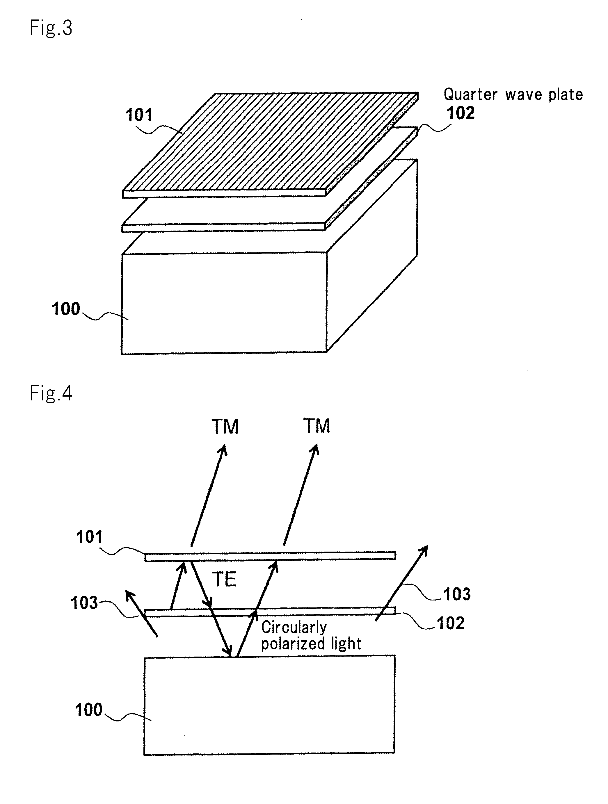
[0143]The light source unit shown in FIG. 17 and FIG. 18 includes wave plate 4 positioned opposite a surface of polarizer 2 which is opposite to an LED 1-side surface of polarizer 2. The second exemplary embodiment is different from the first exemplary embodiment in this regard. LED 1, polarizer 2, and diffraction grating 3 in the second exemplary embodiment are the same as LED 1, polarizer 2, and diffraction grating 3 in the first exemplary embodiment.
[0144]Wave plate 4 polarizes all light rays transmitted through polarizer 2 in a specific direction, and includes, for example, a half λ plate.
[0145]The direction of the optical axis of wave plate 4 varies depending on the position in the plane of wave plate 4. The different optical axes correspond to the respective transmission axes o...
third exemplary embodiment
[0159]In the above-described light source units according to the first and second exemplary embodiments, the recessed and protruding structures of polarizer 2 and diffraction grating 3 are formed from a metal material such as aluminum. However, the recessed and protruding structures may be formed by a technique using a photonic crystal.
[0160]FIG. 22 shows configurations of a polarizer and a diffraction grating which are used in a light source unit according to a third exemplary embodiment.
[0161]As shown in FIG. 22, polarizer 5 includes multilayer film structure 51 and recessed and protruding patterns 52 which have a periodically varying refractive index. Diffraction grating 6 formed from a photonic crystal is formed on recessed and protruding patterns 52. Diffraction grating 6 is formed from radial recessed and protruding patterns.
[0162]In the light source unit according to the third exemplary embodiment, polarizer 5 with diffraction grating 6 shown in FIG. 22 is positioned opposite...
PUM
 Abstract
Description
Claims
Application Information