
Load adaptive variable frequency phase-shift full-bridge dc/dc converter

a phase-shift, adaptive variable frequency technology, applied in the direction of dc-dc conversion, power conversion systems, instruments, etc., can solve the problems of loss of zvs loss of zvs of converters with parallel inductors under heavy loads,

Active Publication Date: 2013-08-29
SPARQ SYST INC
View PDF2 Cites 28 Cited by
  • Summary
  • Abstract
  • Description
  • Claims
  • Application Information

AI Technical Summary

Benefits of technology

The present invention provides a system, method, and circuit for a full-bridge DC / DC converter that can achieve zero voltage switching across all load conditions. This is achieved by controlling the reactive current in the converter and adjusting the switching frequency and phase shift of the converters' leading and lagging legs. The technical effects include improved efficiency, reduced power loss, and improved stability and control of the converter.

Problems solved by technology

However, the full-bridge converter with the series inductor loses its ZVS capability at light loads, and the converter with the parallel inductor loses its ZVS under heavy loads.
Loss of ZVS means extremely high switching losses at high switching frequencies and very high EMI due to the high di / dt of the snubber discharge current.
Loss of ZVS can also cause a very noisy control circuit, which leads to shoot-through and loss of the semiconductor switches.
However, having a large series inductance limits the power transfer capability of the converter and reduces the effective duty ratio of the converter.
Thus, conventional full-bridge converters are not able to ensure ZVS operation at light loads.
This leads to a bulky resonant tank, lower power density, and lower efficiency.
Although this topology seems very suitable for the battery charger application, there are some setbacks related to the auxiliary circuit.
Since the auxiliary circuit should provide enough reactive power to guarantee ZVS at all operating conditions, the peak value of the current flowing through the auxiliary inductor is very high, thereby drastically increasing the MOSFET conduction losses.
Also, due to the fact that the voltage and frequency across the auxiliary inductor is very high, the core losses of this inductor are also high.
In addition, too much reactive current leads to large voltage spikes on the semiconductor switches due to the delay in the body diode turn-on.

Method used


Image

  • Load adaptive variable frequency phase-shift full-bridge dc/dc converter
  • Load adaptive variable frequency phase-shift full-bridge dc/dc converter
  • Load adaptive variable frequency phase-shift full-bridge dc/dc converter

Examples


Embodiment Construction

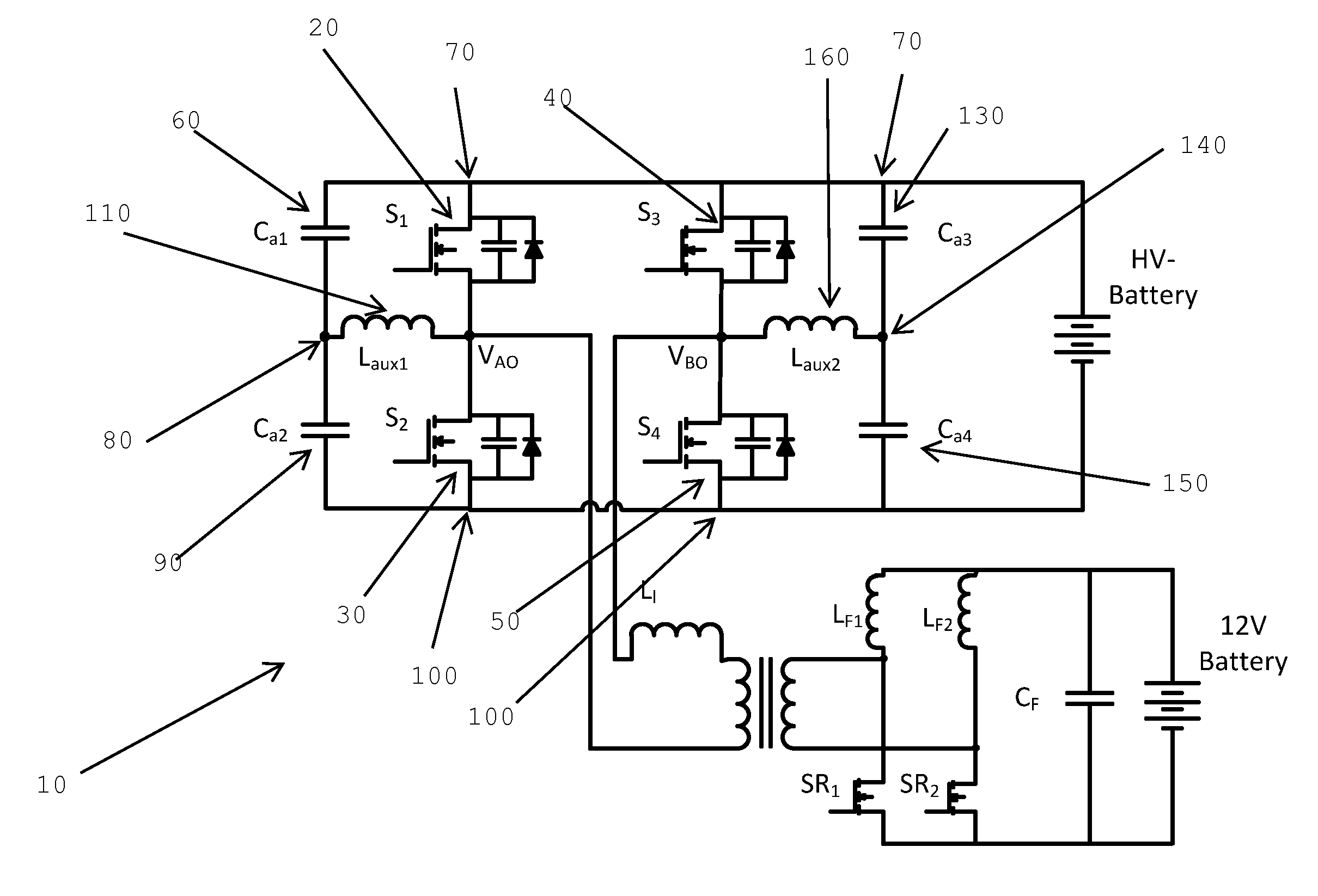
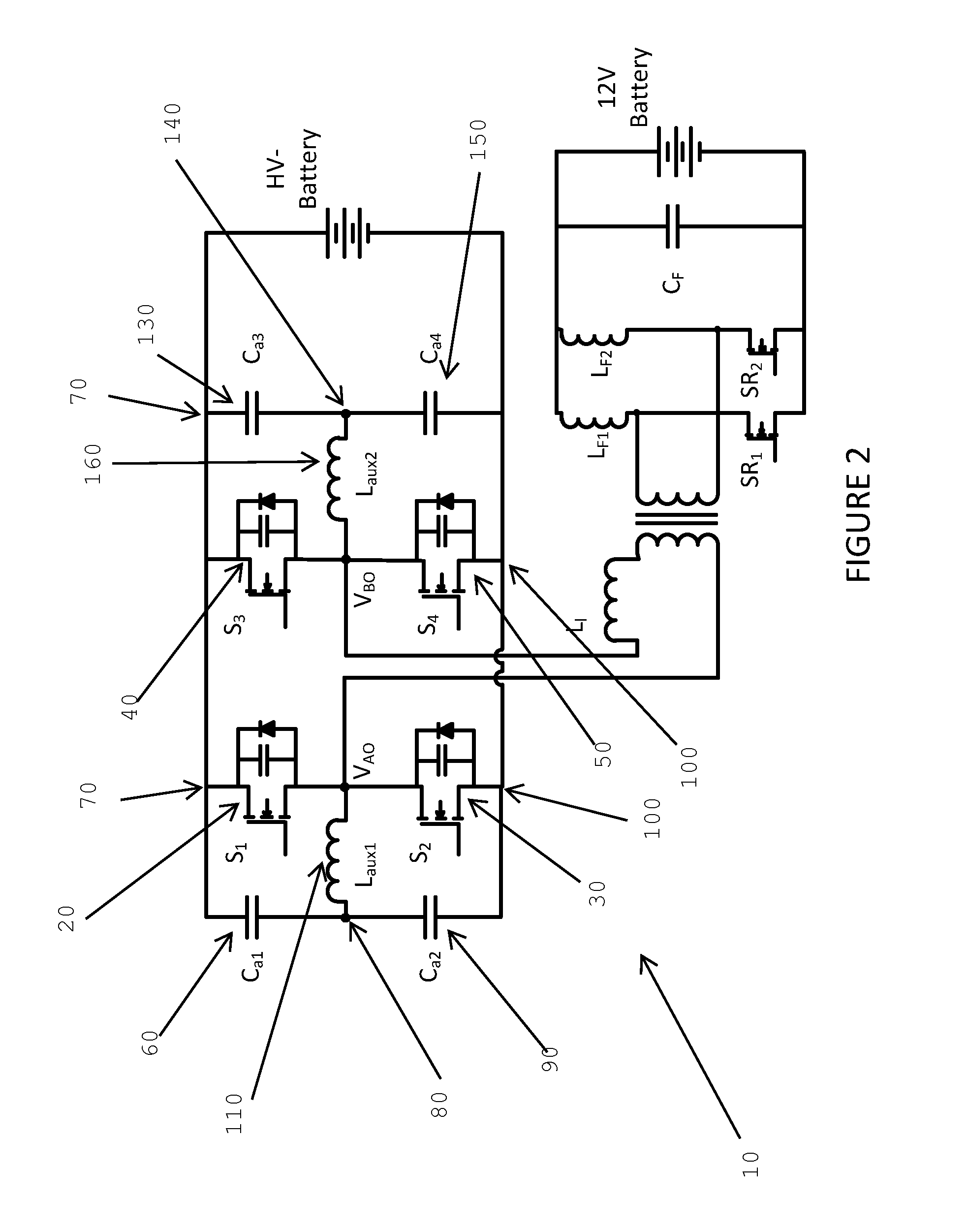
[0052]In one aspect, the invention presents a control method that optimizes the required reactive current provided by the auxiliary circuit. In another aspect, the invention provides a control circuit that adaptively controls the reactive current required to guarantee ZVS under different load conditions. This leads to significantly reduced semiconductor conduction losses as well as reduced auxiliary circuit losses.

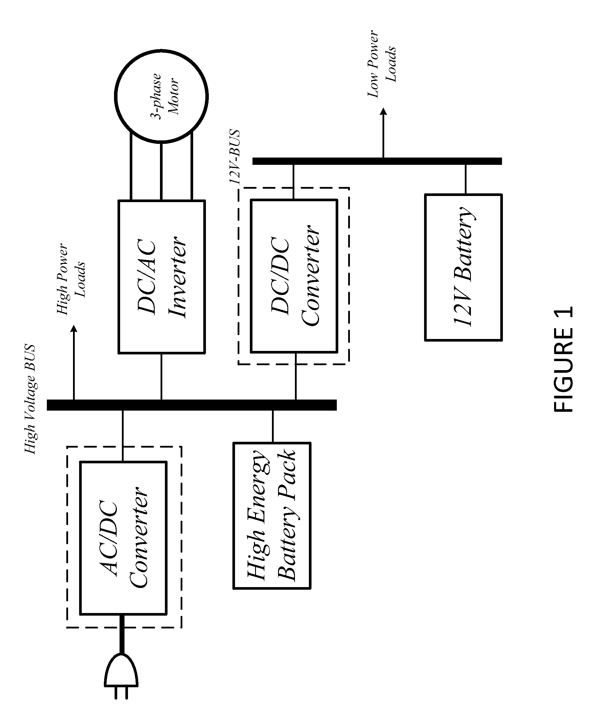
[0053]FIG. 1 is a block diagram of an electric vehicle power conversion system. In this system there are two battery units: a high voltage battery (traction n battery), which feeds the inverter and the electric motor, and a 12V battery. The power conversion system consists of an AC / DC converter, a three-phase DC / AC inverter and a DC / DC converter. The AC / DC converter is a plug-in converter, which charges the high voltage battery. The high voltage battery supplies power to the three-phase inverter which feeds the 3-phase motor. The high voltage battery also charges the 12V b...


PUM


Abstract

Systems, methods, and circuits for providing zero voltage switching conditions across all load conditions in a full-bridge DC / DC converter. An asymmetric auxiliary circuit is provided and the reactive current due to the auxiliary circuit is controlled across various load conditions. This is done by adaptively adjusting the switching frequency of the converter as well as the phase shift of the rising edges of the waveforms for activating the gates in the leading and lagging legs of the full bridge converter.

Description

TECHNICAL FIELD[0001]The present invention relates to power converters. More specifically, the present invention relates to methods, circuits, and devices related to a DC / DC converter which uses a variable switching frequency and phase shift to ensure zero voltage switching conditions for its MOSFETs.BACKGROUND OF THE INVENTION[0002]The drive for environmentally friendly vehicles has led to multiple innovations in the recent past. One of the major areas of research which has led to the viability of electric vehicles is in power systems and, more specifically, in the power systems used to charge the batteries in these electric or sometimes hybrid vehicles. Such power systems generally include DC / DC converters which convert DC power from one voltage into another, more useful, voltage.[0003]Full-bridge topology is the most popular topology used in the power range of a few kilowatts (1-5 KW) for DC / DC converters. Since the switch ratings are optimized for the full-bridge topology, this ...

Claims


Application Information

Patent Timeline
IPC IPC(8): H02M3/335
CPCH02M3/337H02M3/33573H02M3/01
Inventor PAHLEVANINEZHAD, MAJIDJAIN, PRAVEEN
Owner SPARQ SYST INC
Learn More