
Electromagnetic Wave Absorber Using A Dielectric Loss Sheet, Method For Forming The Electromagnetic Wave Absorber, And Rotary Blade For A Wind Turbine Having An Electromagnetic Wave Function Using Same

a dielectric loss sheet and electromagnetic wave technology, applied in wind turbines, wind energy generation, liquid fuel engine components, etc., can solve the problems of increasing the weight of the structure, and poor mechanical and chemical properties of single or composite lossy materials used in the absorption layer, so as to avoid radar interference, avoid mechanical and chemical environment, and broaden the absorption bandwidth

Inactive Publication Date: 2013-08-29
KOREA INST OF MACHINERY & MATERIALS
View PDF0 Cites 19 Cited by
  • Summary
  • Abstract
  • Description
  • Claims
  • Application Information

AI Technical Summary

Benefits of technology

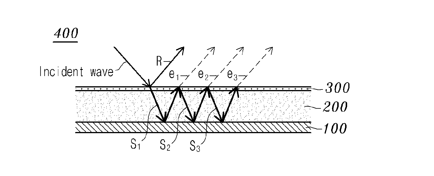
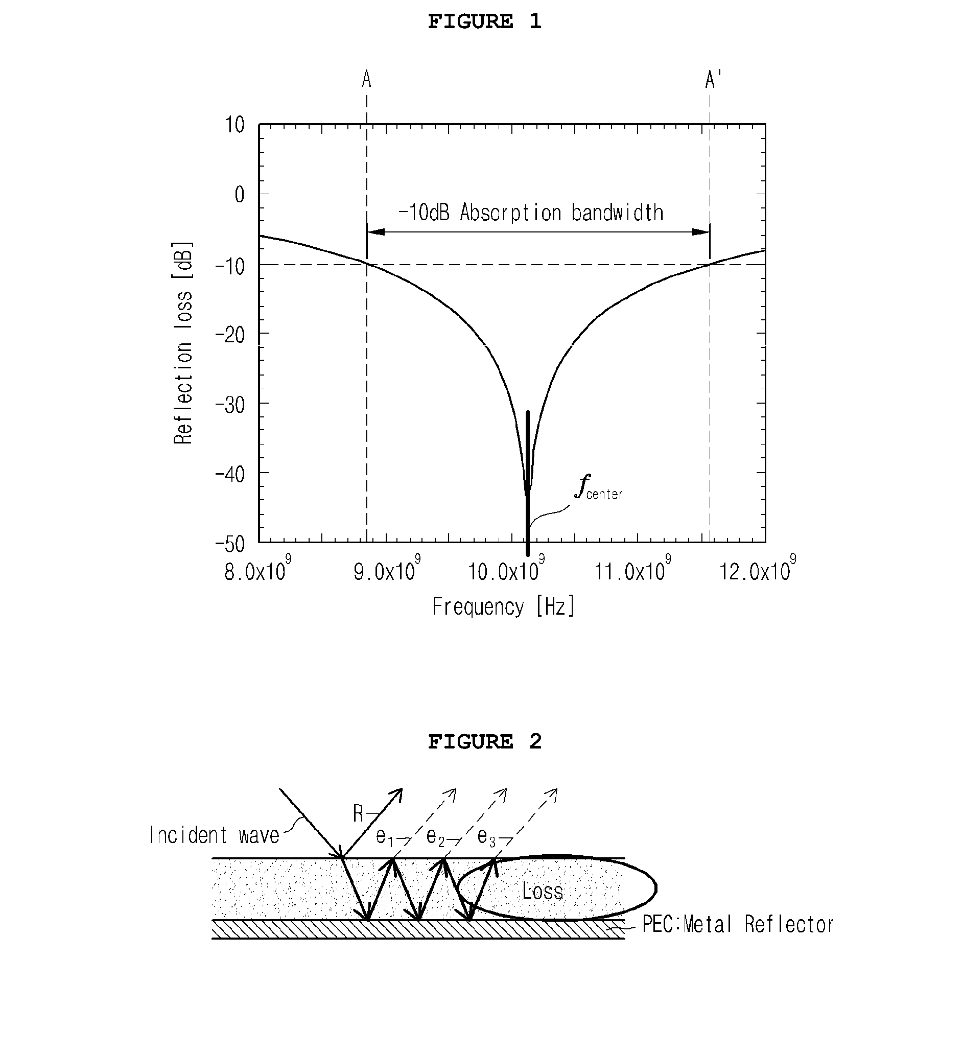
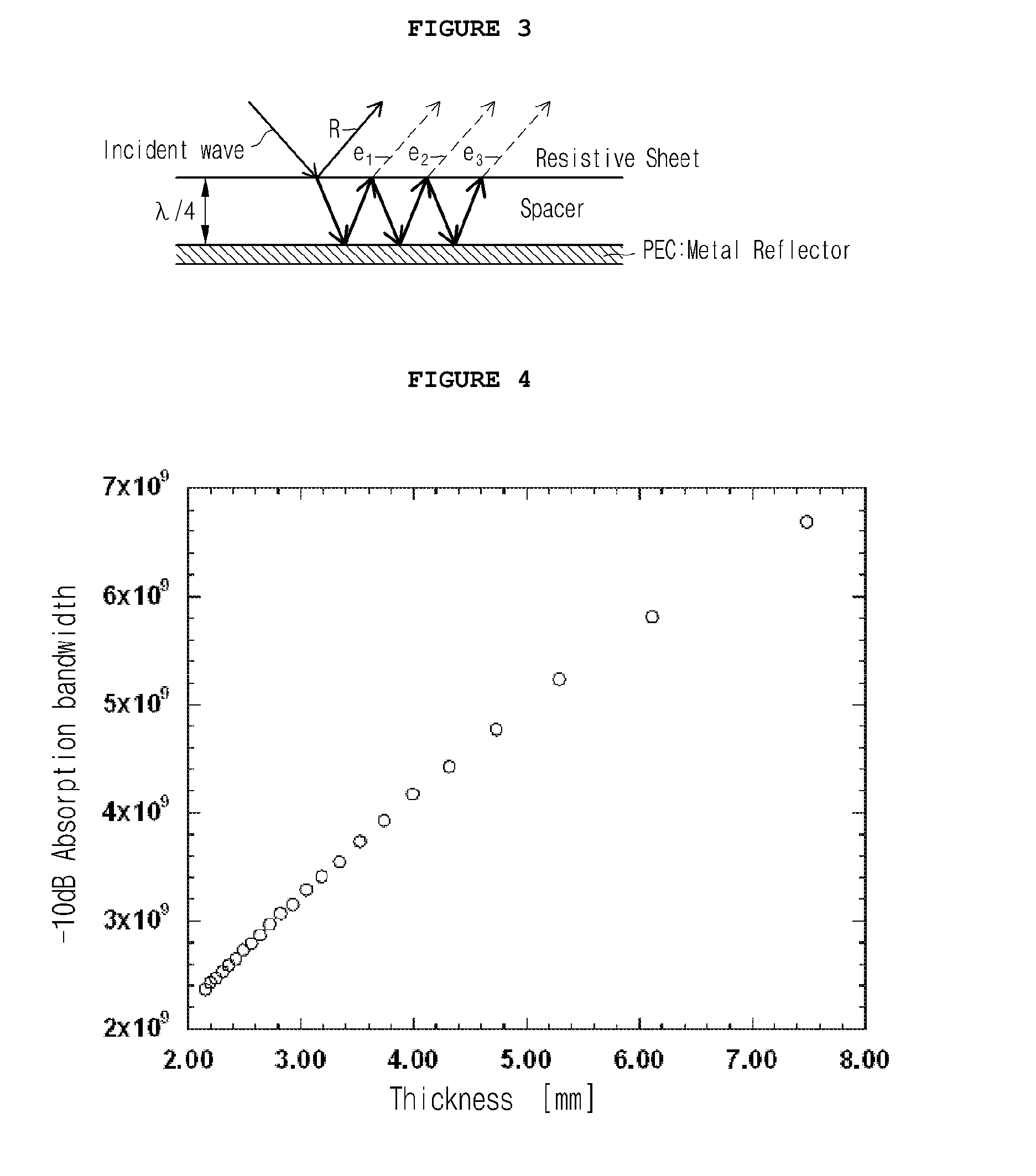
The present invention describes a method for making an electromagnetic wave absorber that has a wide absorption bandwidth and a narrow matching thickness of the support layer. This absorber can be used in wind turbine blades to avoid radar interference without requiring an additional absorber, reducing production costs, fabrication time, and maintenance. The method utilizes a dielectric material commonly used in wind turbine blades as a support layer for the absorber. Overall, the invention provides a solution for reducing electromagnetic interference in wind turbines.

Problems solved by technology

On the whole, a Dallenbach absorber has an absorption layer as thick as several millimeters which may require a large quantity of materials when it is used over a large area, and the single or composite lossy materials used in the absorption layer are poor in mechanical and chemical properties.
Thus, the conventional absorption layer suffers from the disadvantage of increasing the weight of the structure and being vulnerable to mechanical and chemical environments.

Method used


Image

  • Electromagnetic Wave Absorber Using A Dielectric Loss Sheet, Method For Forming The Electromagnetic Wave Absorber, And Rotary Blade For A Wind Turbine Having An Electromagnetic Wave Function Using Same
  • Electromagnetic Wave Absorber Using A Dielectric Loss Sheet, Method For Forming The Electromagnetic Wave Absorber, And Rotary Blade For A Wind Turbine Having An Electromagnetic Wave Function Using Same
  • Electromagnetic Wave Absorber Using A Dielectric Loss Sheet, Method For Forming The Electromagnetic Wave Absorber, And Rotary Blade For A Wind Turbine Having An Electromagnetic Wave Function Using Same

Examples


Embodiment Construction

[0090]Reference should now be made to the drawings, throughout which the same reference numerals are used to designate the same or similar components. Below, a description will be given of preferred embodiments of the present invention in conjunction with the accompanying drawings. Throughout the accompanying drawings, the same reference numerals are used to designate the same or similar components. It should be apparent to those skilled in the art that, although many specified elements such as concrete components are elucidated in the following description, they are intended to aid the general understanding of the invention and the present invention can be implemented without the specified elements. Further, in the description of the present invention, when it is determined that the detailed description of the related art would obscure the gist of the present invention, the description thereof will be omitted.

[0091]Unless the context clearly requires otherwise, throughout the descr...


PUM

PropertyMeasurementUnit
electromagnetic wave reflectivityaaaaaaaaaa
center frequencyaaaaaaaaaa
thicknessaaaaaaaaaa

Abstract

Disclosed are an electromagnetic wave absorber using a dielectric loss sheet, a method for fabricating the same, and a wind turbine blade having an electromagnetic wave function. The electromagnetic wave absorber comprises: a support layer for providing a resonant space of electromagnetic waves; a highly conductive backing layer assigned to a back surface of the dielectric support layer; and a dielectric lossy composite sheet layer formed on a front surface of the dielectric support layer, said dielectric lossy composite sheet layer having such a dielectric permittivity so as to generate a resonant peak with the electromagnetic waves reflected from the highly conductive backing layer.

Description

TECHNICAL FIELD[0001]The present invention relates to absorption and shielding of electromagnetic waves. More particularly, the present invention relates to an electromagnetic wave absorber which exhibits a broad absorption bandwidth and has a thin support layer necessary for matching thereof, while retaining the advantage of a Salisbury screen-type absorber in terms of fabrication and structure, and to a method for fabricating the same.[0002]Also, the present invention is concerned with a wind turbine blade having an electromagnetic wave absorption function, and a method for the fabrication thereof, wherein the wind turbine blade having an electromagnetic wave absorption function comprises an electromagnetic wave absorber the dielectric support layer of which employs a part of a composite for a turbine blade.BACKGROUND ART[0003]With the development of various electromagnetic devices operating in a high-frequency band, the wireless communication market has rapidly been expanded in r...

Claims


Application Information

Patent Timeline
Patent Type & Authority Applications(United States)
IPC IPC(8): G12B17/02C09J5/00F03D11/00B32B37/24
CPCF05B2260/99B32B37/24C09J5/00F03D11/00H05K9/0088Y02E10/722H05K9/0083H05K9/0084G12B17/02F03D1/06F03D80/00Y02E10/72
Inventor KIM, JIN BONGKIM, BYUNG SUNBYUN, JOON HYUNGHWANG, BYUNG SUNUM, MOON KWANGPARK, JI SANG
Owner KOREA INST OF MACHINERY & MATERIALS
Learn More