Substrate treatment apparatus and substrate treatment method

a technology of substrate and treatment apparatus, applied in the direction of spraying apparatus, coating, chemical vapor deposition coating, etc., can solve the problem of damage to a portion of the front surface of the wafer, and achieve the effect of treating uniformly

Active Publication Date: 2013-08-29
DAINIPPON SCREEN MTG CO LTD
View PDF4 Cites 44 Cited by
  • Summary
  • Abstract
  • Description
  • Claims
  • Application Information

AI Technical Summary

Benefits of technology

[0123]With this arrangement, the chemical liquid is supplied at a first flow rate onto the major surface of the substrate held by the substrate holding unit and, at the same time, the substrate is rotated at the first rotation speed, whereby the chemical liquid film is formed on the major surface of the substrate as covering the major surface. Thereafter, the rotation speed of the substrate is reduced to the second rotation speed, whereby the chemical liquid film is continuously retained on the major surface of the substrate. With the liquid film thus retained, the heater is located in opposed relation to the major surface of the substrate and the heating by the heater is started, whereby the chemical

Problems solved by technology

However, the irradiation with the oxygen plasma for the ashing of the resist damages a portion of the front

Method used


Image

  • Substrate treatment apparatus and substrate treatment method
  • Substrate treatment apparatus and substrate treatment method
  • Substrate treatment apparatus and substrate treatment method

Examples


second embodiment

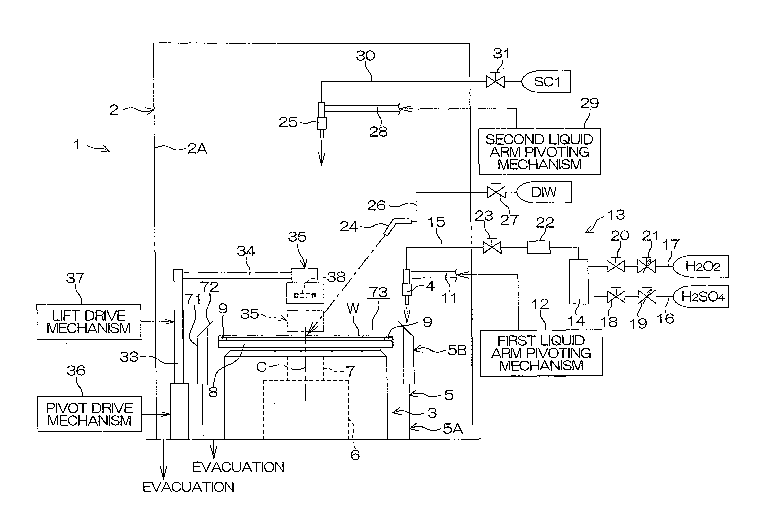
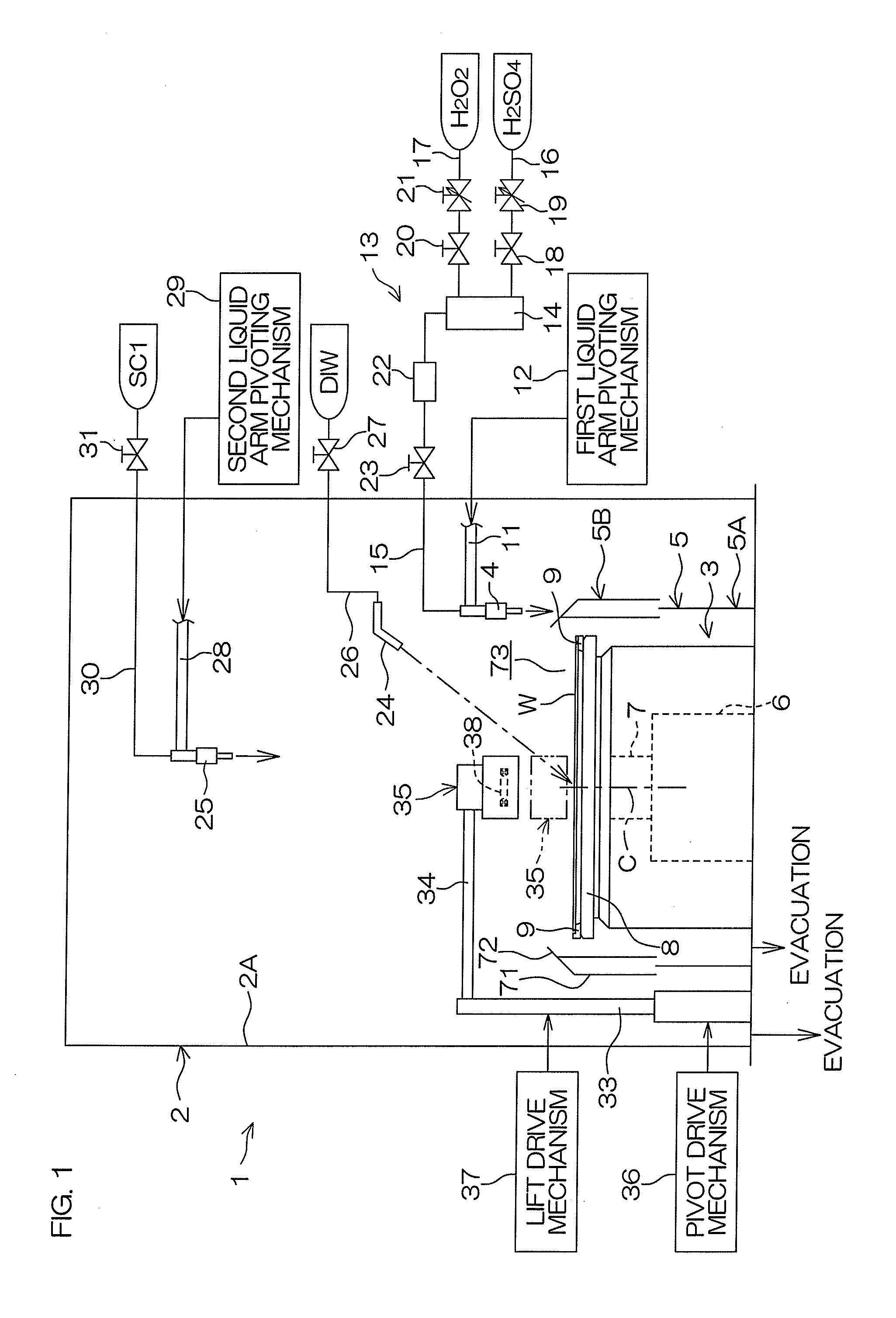
[0286]FIG. 19 is a diagram schematically showing the construction of a substrate treatment apparatus 1A according to the present invention. In FIG. 19, components corresponding to those shown in FIG. 1 described above will be designated by the same reference characters as in FIG. 1, and duplicate description will be omitted. Reference will be made again to FIGS. 3, 5, 6, 7, 8 and 10 for description of this embodiment.

[0287]The substrate treatment apparatus 1A is an apparatus of a single wafer treatment type to be used, for example, in a resist removing process for removing an unnecessary resist from a front surface (major surface) of a wafer W (an example of a substrate) after an ion implantation process for implanting an impurity into the front surface of the wafer W or after a dry etching process.

[0288]The substrate treatment apparatus 1A includes a wafer rotating mechanism (substrate holding unit) 3 which holds and rotates the wafer W, a lift-off liquid nozzle (chemical liquid su...

first embodiment

[0330]After the supply of the DIW is continued for a predetermined rinsing period, the DIW valve 27 is closed to stop supplying the DIW onto the front surface of the wafer W. In the intermediate rinsing step of Step S5 and the rinsing step of Step S7, the rinse liquid is not limited to the DIW, but carbonated water, electrolytic ion water, ozone water, reduced water (hydrogen water), magnetic water or the like may be used as in the

[0331]After a lapse of a predetermined period from the start of the rinsing step, the controller 55 closes the DIW valve 27 to stop supplying the DIW onto the front surface of the wafer W. Thereafter, the controller 55 drives the motor 6 to increase the rotation speed of the wafer W to a predetermined higher rotation speed (e.g., 1500 to 2500 rpm), whereby a spin drying process is performed to spin off the DIW from the wafer W to dry the wafer W (Step S8 in FIG. 7). In the spin drying process of Step S8, DIW adhering to the wafer W is removed from the wafe...

third embodiment

[0342]In the heater head 135 of the third embodiment, a vertically extending round suction pipe 192 is inserted in an inert gas flow pipe 191 (gas flow pipe). Thus, the inert gas flow pipe 191 and the suction pipe 192 form a double pipe structure 190.

[0343]In the heater head 135 of the third embodiment, the suction pipe 192 has a suction port 194 provided in a lower surface (opposed surface) 150B of a lower baffle plate 150. The lower baffle plate 150 has substantially the same structure as the lower baffle plate 100 shown in FIG. 20, except that the suction port 194 is provided therein. An annular inert gas outlet port (gas outlet port) 151 directed outward is defined between a peripheral edge of an upper surface 150A of the lower baffle plate 150 and the peripheral edge of the lower surface 52B of the bottom plate 52.

[0344]The inert gas flow pipe 191 is a round pipe (cylindrical pipe) having greater inner and outer diameters than the inert gas flow pipe 90 (see FIG. 20). A distal ...


PUM

PropertyMeasurementUnit
Temperatureaaaaaaaaaa
Flow rateaaaaaaaaaa
Diameteraaaaaaaaaa

Abstract

A substrate treatment apparatus is used for treating a major surface of a substrate with a chemical liquid. The substrate treatment apparatus includes: a substrate holding unit which holds the substrate; a chemical liquid supplying unit having a chemical liquid nozzle which supplies the chemical liquid onto the major surface of the substrate held by the substrate holding unit; a heater having an infrared lamp to be located in opposed relation to the major surface of the substrate held by the substrate holding unit to heat the chemical liquid supplied onto the major surface of the substrate by irradiation with infrared radiation emitted from the infrared lamp, the heater having a smaller diameter than the substrate; and a heater moving unit which moves the heater along the major surface of the substrate held by the substrate holding unit.

Description

BACKGROUND OF THE INVENTION[0001]1. Field of the Invention[0002]The present invention relates to a substrate treatment apparatus for treating a substrate with a hot chemical liquid. Examples of the substrate to be treated include semiconductor wafers, substrates for liquid crystal display devices, substrates for plasma display devices, substrates for FED (Field Emission Display) devices, substrates for optical disks, substrates for magnetic disks, substrates for magneto-optical disks, substrates for photo masks, ceramic substrates and substrates for solar cells.[0003]2. Description of Related Art[0004]Semiconductor device production processes include the step of locally implanting an impurity (ions) such as phosphorus, arsenic or boron, for example, into a major surface (front surface) of a semiconductor wafer (hereinafter referred to simply as “wafer”). In order to prevent the ion implantation into an unnecessary portion of the wafer, a resist pattern of a photosensitive resin is f...

Claims


Application Information

Patent Timeline
IPC IPC(8): H01L21/02H01L21/306
CPCH01L21/31111H01L21/6708H01L21/67023H01L21/30604H01L21/0206H01L21/02282H01L21/302H01L21/306C23C16/46C23C16/48C23C16/481C23C16/482
Inventor NEGORO, SEIMURAMOTO, RYOHAYASHI, TOYOHIDEHASHIMOTO, KOJINAGAI, YASUHIKO
Owner DAINIPPON SCREEN MTG CO LTD
Why Eureka
Try Eureka