Method for manufacturing a flexible intraocular retinal implant having doped diamond electrodes

a technology of diamond electrodes and flexible electrodes, which is applied in the field of flexible retinal implants, can solve the problems of brittle electrodes, damage to retinal tissues, and certain implants, and achieve the effects of improving the stability of the implant, improving the implant quality, and improving the implant quality

Active Publication Date: 2013-09-05
COMMISSARIAT A LENERGIE ATOMIQUE ET AUX ENERGIES ALTERNATIVES +1
View PDF12 Cites 15 Cited by
  • Summary
  • Abstract
  • Description
  • Claims
  • Application Information

AI Technical Summary

Benefits of technology

[0038]The doping of the diamond makes it possible to render the material electrically conductive, in order to be able to use it to convey the electrical signals that will serve for the cell stimulation. The diamond may be doped with any material and in sufficient quantities to make the doped diamond electrically conductive. Preferably, the doped diamond is diamond doped with boron. It is in fact known that diamond doped with boron has excellent electrochemical, biocompatibility and mechanical stability properties, which makes it an ideal material for producing the electrodes of our implant. Preferably, the boron concentration in the doped diamond is comprised between 1018 and 1021 atoms per cm3.
[0060]The method according to the invention makes it possible to manufacture an intraocular retinal implant including both a flexible substrate and electrodes made of doped diamond. The fact that the substrate is flexible makes it possible to obtain an implantation that is not very invasive, as well as a better contact with the tissues by hugging as best as possible the shape of the retina. Obtaining a better contact makes it possible, among other things, to use lower levels of stimulation currents, which ultimately leads to an increase in the geometric resolution of the implant.
[0061]The implant produced according to the method of the invention may be implanted on or under the retina for several years without creating any modification of the surrounding tissues (no formation of glial cells or necrosis of the tissues, etc.). The performance of the implant does not degrade over time, thereby avoiding any subsequent intervention aiming to change or to modify the implant.
[0062]This implant can make it possible to produce an artificial retina. It is adapted to an implantation in living retinal tissues to enable, for example, the restoration of sight in certain patients affected by degeneration of their photoreceptors.
[0063]It is possible to produce planar implants in which the distal ends of the electrodes are substantially at the same level as the surface of the flexible plate on which they are located; it is also possible to produce implants in which the electrodes have a three-dimensional structure and are projecting from the flexible plate on which they are arranged, which allows them to reach more easily the areas of specific interest in the retinal tissue and to ensure an anchoring in the tissues, thereby avoiding a movement of the implant by sliding on the cellular tissues of the retina. The three-dimensional structures of the electrodes may be any elongated shape, such as for example a cylindrical, pyramidal, conic, parallelepiped shape, etc.

Problems solved by technology

Yet, these types of implants have a certain number of drawbacks.
Firstly, their rigidity can damage the retinal tissues during their implantation on or under the retina.
In certain cases, the electrode may moreover be brittle.
In addition, the lack of flexibility of said implants does not make it possible to obtain a suitable positioning of the implants and in particular to hug correctly the surface of the tissues to be stimulated, which can potentially prevent certain electrodes from coming into contact with the areas of interest to stimulate.
Yet, one of the drawbacks of electrodes manufactured on the basis of said materials is that they suffer from corrosion and from a lack of mechanical and chemical stability, in particular in in-vivo medium, which is a relatively hostile medium for metal electrodes.
In fact, the use of metal electrodes in the implants imposes the application of high levels of stimulation currents, which induces, in the long term, a premature ageing of the electrodes and requires a ponderous surgical intervention in order to replace the worn out implant.
Firstly, the reduction in the size of the electrodes leads to a loss of the capacitance thereof. To resolve this problem, it is necessary to structure the surface of the electrodes in order to increase the specific surface thereof, which is very difficult to achieve on metal electrodes. A possible solution to this problem is to produce the metal electrodes with platinum black, in other words with a stack of platinum particles of nanometric sizes. However, the mechanical strength of this type of electrode is very poor, in particular when they are in contact with living tissues.
Secondly, bringing the electrodes closer together can cause interferences between adjacent electrodes and thereby lead to a loss of resolution of the implant. One way of reducing said potential interferences is to apply less current to the electrodes. However, by reducing the current, the electrodes may then only efficiently stimulate the neuronal cells provided that said cells are as close as possible to the electrodes, or even in direct contact with them. To do this, the electrodes must be constituted of a biocompatible material. A biocompatible material is a material that does not cause necrosis of the surrounding tissues and which has moreover a large affinity with the cells to be stimulated, in other words which is favourable to the coupling of neuronal cells directly on its surface. It is known for example that, in the case of retinal implants, when metal electrodes are used, there is formation of a layer of glial cells that insert themselves between the surface of the electrode and the neuronal tissues, which affect electrical transmission between the neurones and the electrode.
However, electrodes based on nanotubes are very fragile and have a tendency to break on contact with the biological tissues and become uncoupled, through friction, from the support substrate on which they are arranged.
The deposition is thus carried out at a temperature comprised typically between 500 and 1000° C. Yet, said temperature scale is incompatible with the growth of synthetic diamond on the flexible substrates made of polymers commonly used for the production of flexible implants.
The production of said implants thus seems compromised.

Method used


Image

  • Method for manufacturing a flexible intraocular retinal implant having doped diamond electrodes
  • Method for manufacturing a flexible intraocular retinal implant having doped diamond electrodes
  • Method for manufacturing a flexible intraocular retinal implant having doped diamond electrodes

Examples


Embodiment Construction

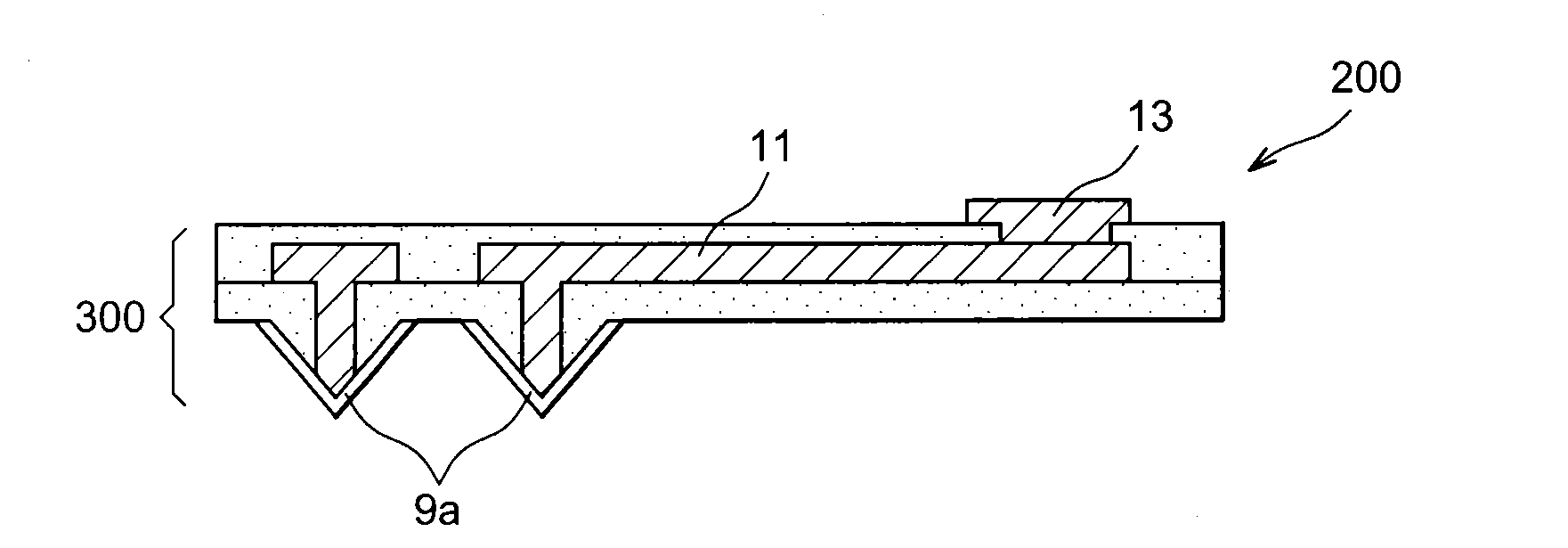
[0017]The subject matter of the invention is thus a method for manufacturing an intraocular retinal implant, intended to stimulate cells of the retina by sending electrical impulses to produce an artificial vision, said implant including a flexible plate made of a biocompatible and electrically insulating material, which is provided, on one of the face thereof, with a plurality of electrodes made of doped diamond spaced apart from each other and connected to interconnection lines intended to lead an electric current to the electrodes so that they can transmit electrical impulses to said cells of the retina, said method including the following successive steps:

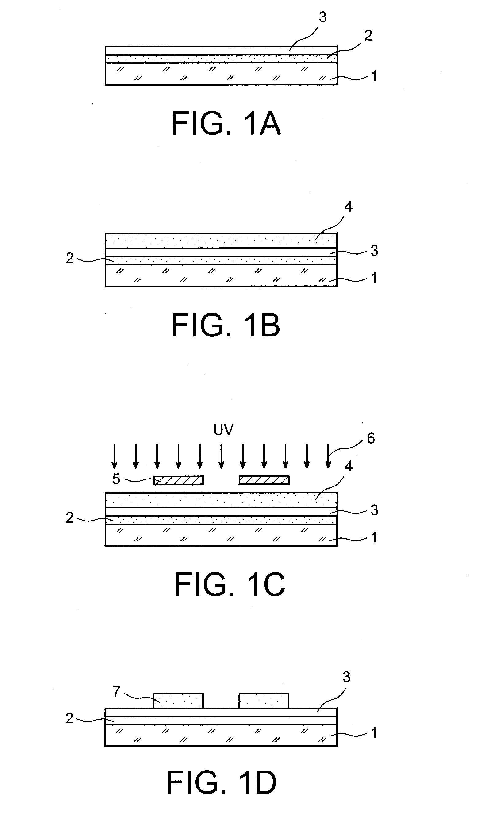
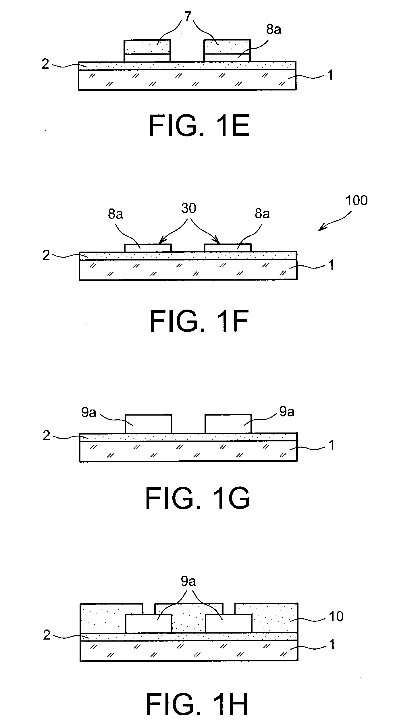
[0018]providing a mould capable of supporting the growth of a layer of doped diamond, said mould comprising, on one of the face thereof, a set of elements which are all depressed or all projecting with respect to the surface of said face, and which constitute a pattern cavity for the electrodes of the implant which it is desire...


PUM

PropertyMeasurementUnit
sizeaaaaaaaaaa
sizeaaaaaaaaaa
temperatureaaaaaaaaaa

Abstract

A method for manufacturing an intraocular retinal implant including: providing a mold capable of supporting growth of a layer of doped diamond, the mold including, on one face, elements all depressed or all projecting with respect to the surface of the face, and constituting a pattern cavity for the electrodes of the implant which it is desired to obtain; producing the doped diamond electrodes by growing a layer of doped diamond in all or part of a space occupied by the pattern cavity elements; forming a first insulating layer on the face of the mold including the pattern cavity; producing interconnection lines by depositing an electrically conductive material at least in spaces not covered by the first insulating layer; forming a second insulating layer on the mold face including the pattern cavity, the second layer covering the interconnection lines, the first and second insulating layers forming a flexible plate of the implant; removing the mold.

Description

TECHNICAL FIELD[0001]The present invention relates to the field of implants, the function of which is to restore the vision of patients made blind by a degenerative disease of the retina.[0002]The invention more particularly relates to a method for manufacturing a flexible retinal implant intended to be implanted in the eyeball of a patient and the function of which is to receive and process external visual stimuli that are used to excite the diseased retina of the patient via electrodes.[0003]It is pointed out that the method according to the invention may be applied indiscriminately to the production of “epi-retinal” implants, in other words intended to be arranged on the retina of the patient, or to the production of “sub-retinal” implants, in other words intended to be placed behind the retina.PRIOR ART[0004]Today, retinal degeneration pathologies, such as for example age related macular degeneration (ARMD), affect around 12 million people in the United States and in Europe. Cer...

Claims


Application Information

Patent Timeline
Patent Type & Authority Applications(United States)
IPC IPC(8): H01L21/64
CPCA61N1/0543A61N1/36046H01L21/02444H01L21/02527H01L21/02579H01L21/64H01L21/0262H01L21/02628H01L21/02639H01L29/1602H01L29/45H01L21/02601
Inventor SCORSONE, EMMANUELBERGONZO, PHILIPPEBONNAURON, MATHIAS
Owner COMMISSARIAT A LENERGIE ATOMIQUE ET AUX ENERGIES ALTERNATIVES
Why Eureka
Try Eureka