Magnetic field gradient monitor and magnetic field gradient waveform correction apparatus and methods

a gradient monitor and magnetic field technology, applied in the field of magnetic resonance imaging, can solve problems such as quantitative velocity errors, image quality problems, and limited gradient waveform duration

Active Publication Date: 2013-09-12
GREEN IMAGING TECH
View PDF1 Cites 17 Cited by
  • Summary
  • Abstract
  • Description
  • Claims
  • Application Information

AI Technical Summary

Benefits of technology

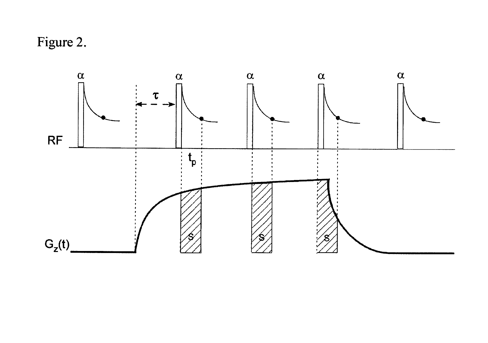
[0009]Compared with the prior art frequency encode magnetic field monitoring with nuclear magnetic resonance (“NMR”) microprobes, pure phase encode detection with RF microprobes has distinct advantages: (i) there is no T2* decay limitation on the waveform measurement and thus measurements of long duration gradient waveforms are possible; (ii) gradient dephasing is avoided by decomposing the large gradient area into small separate gradient areas with short time interval tp and thus there is no limit on the k-space maxima or net gradient area maxima; (iii) it allows measurement of high amplitude gradients for imaging and diffusion; and (iv) simple probe construction is possible since susceptibility matching probe components are not required.

Problems solved by technology

The residual eddy currents may however still cause image-quality problems [1] including ghosting in echo planar imaging (“EPI”), rapid acquisition with refocused echo (“RARE”) and gradient and spin echo (“GRASE”) imaging pulse sequences [2], slice-profile modulation with spatial-spectral RF pulses [3], geometric distortion in diffusion-weighted EPI [4], and quantitative velocity errors in phase-contrast imaging [5].
However, the gradient waveform duration is limited by the sample T2*.
In addition, implementation of this technique is relatively complex as it requires careful probe fabrication, an array of at least 3 probes, accurate probe positioning and alignment and a multi channel receiver.

Method used


Image

  • Magnetic field gradient monitor and magnetic field gradient waveform correction apparatus and methods
  • Magnetic field gradient monitor and magnetic field gradient waveform correction apparatus and methods
  • Magnetic field gradient monitor and magnetic field gradient waveform correction apparatus and methods

Examples


Embodiment Construction

[0036]Two trial gradient waveforms illustrate the advantages of the method of this invention. Neither could be measured by conventional MFM. One illustrates the ability to measure extended duration magnetic field gradient waveforms while the other illustrates the ability to measure magnetic field gradient waveforms with large net gradient area and / or high amplitude (a simple bipolar diffusion gradient waveform, Gmax=250 mT / m, b value approx=100,000 s / mm2).

[0037]The RF micro coil utilized is extremely easy to fabricate, compared with MFM RF microprobes [15-16]. Susceptibility matching for improved static field homogeneity is not an issue. One small probe is sufficient to measure all three gradient axes and a multi channel receiver is not a prerequisite. The method is a point monitor where the probe location does not need to be exactly known.

[0038]The RF micro coil utilized provides a high measurement sensitivity compared to prior art [17] due to the maximized probe filling factor and...


PUM


Abstract

Method for correcting the magnetic field gradient waveform in a magnetic resonance measurement including extracting an impulse response from the measured step response of a magnetic resonance system, determining the slew rate of the system during the step response measurement, modifying the desired output waveform such that the desired output waveform is constrained to within the slew rate and the bandwidth of the system, and determining the required pre-equalized input waveform.

Description

CROSS-REFERENCE TO RELATED APPLICATIONS[0001]This application is a Continuation-in-Part of U.S. application Ser. No. 13 / 003,509 filed Mar. 29, 2011.FIELD OF THE INVENTION[0002]The present invention relates to magnetic resonance imaging (“MRI”) generally, and pure phase encode magnetic field gradient monitoring and magnetic field gradient waveform correction in particular.BACKGROUND OF THE INVENTION[0003]Magnetic field gradients play a central role in magnetic resonance (“MR”) imaging. Their functions include encoding spatial information and sensitizing the image contrast to coherent or incoherent motion. Fast, efficient MRI measurements rely on magnetic field gradient waveforms with high temporal fidelity.[0004]Rapid switching of the magnetic field gradients leads to rapidly changing magnetic flux through the radio frequency (“RF”) coil, RF shield, main magnet components and other structures. This changing magnetic flux leads to eddy currents being induced in conducting pathways nea...

Claims


Application Information

Patent Timeline
Patent Type & Authority Applications(United States)
IPC IPC(8): G01R33/54
CPCG01R33/56572G01R33/54G01R33/58G01R33/3852
Inventor GOORA, FREDERICBALCOM, BRUCE
Owner GREEN IMAGING TECH
Why Eureka
Try Eureka