Abrasive particles having complex shapes and methods of forming same

a technology of abrasive particles and shapes, applied in the field of can solve the problems of unreliable typical techniques for forming structured abrasive articles, slow production, and performance limitations

Active Publication Date: 2013-09-12
SAINT GOBAIN CERAMICS & PLASTICS INC
View PDF11 Cites 109 Cited by
  • Summary
  • Abstract
  • Description
  • Claims
  • Application Information

AI Technical Summary

Benefits of technology

[0023]In one aspect, a shaped abrasive particle includes a body having a length (l), a width (w), and a height (h), wherein the body has a three-pointed star including a first arm defining a first arm, a second arm defining a

Problems solved by technology

However, there is often a trade-off between removal rate and surface quality.
Lower stock removal rates lead to slower production and increased cost.
However, typical techniques for forming structured abrasive articles are unreliable and suffer from performance limitations.
Imperfect coating of the viscous binder with functional powder leads to binder sticking on patterning tools.
Binder sticking produces poor structures, leading to poor product performance and wasted product.
Selection of binders appropriate for typical structured abrasive formation techniques is limited by the process.
For example, high loading of traditional fillers may adve

Method used


Image

  • Abrasive particles having complex shapes and methods of forming same
  • Abrasive particles having complex shapes and methods of forming same
  • Abrasive particles having complex shapes and methods of forming same

Examples


example 1

[0296]A mixture in the form of a gel is obtained having approximately 42% solids loading of boehmite commercially available as Catapal B from Sasol Corp. combined with 58 wt % water containing a minority content of nitric acid and organic additives. The gel has a viscosity of approximately 3×10³ to 4×10⁴ Pa·s and a storage modulus of 3×10⁴ to 2×10⁵ Pa.

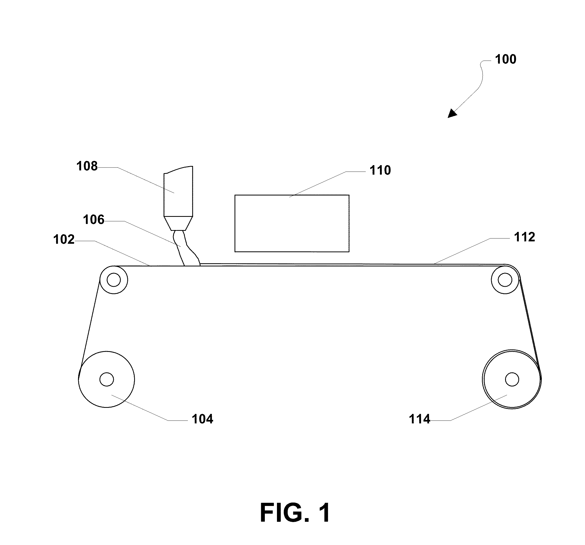
[0297]The gel is extruded from a die using a pressure of up to 80 psi (552 kPa) onto a mold blank of polycarbonate and into a plurality of openings, wherein each of the openings are in the shape of a three-pointed star. The surfaces of the openings within the mold blank have been coated with canola oil. The openings define three-pointed star two-dimensional shapes having a length of approximately 5-7 mm, a width of 3-5 mm, and a depth of approximately 0.8 mm. The openings have tip angles of approximately 35 degrees, and an interior angle between the three arms of approximately 225 degrees.

[0298]The gel is extruded into the openings and...

example 2

[0299]The process of Example 1 was used with the exception that the mold blank utilized openings defining a four-point star shaped two-dimensional shape having a length of approximately 7-9 mm, a width of 7-9 mm, and a depth of approximately 0.8 mm. The openings have tip angles of approximately 25 degrees, and an interior angle between the three arms of approximately 250 degrees. FIG. 66A is an image of a representative particle formed from Example 2. The body has a curling factor of less than 5.

example 3

[0300]The process of Example 1 was used with the exception that the mold blank utilized openings defining a cross-shaped two-dimensional shape having a length of approximately 5-6 mm, a width of 5-6 mm, and a depth of approximately 0.8 mm. The arms have a width of approximately 2 mm and a length of approximately 1 mm. FIG. 67 is an image of a representative particle formed from Example 3. The body has a curling factor of less than 5.

[0301]The present application represents a departure from the state of the art. While the industry has recognized that shaped abrasive particles may be formed through processes such as molding and screen printing, the processes of the embodiments herein are distinct from such processes. Moreover, the resulting shaped abrasive particles have one or a combination of distinct features from particles formed according to conventional approaches. The shaped abrasive particles of the embodiments herein can have a particular combination of features distinct from...


PUM

PropertyMeasurementUnit
Fractionaaaaaaaaaa
Angleaaaaaaaaaa
Angleaaaaaaaaaa

Abstract

An abrasive grain is disclosed and may include a body. The body may define a length (l), a height (h), and a width (w). In a particular aspect, the length is greater than or equal to the height and the height is greater than or equal to the width. Further, in a particular aspect, the body may include a primary aspect ratio defined by the ratio of length:height of at least about 2:1. The body may also include an upright orientation probability of at least about 50%.

Description

CROSS-REFERENCE TO RELATED APPLICATION(S)[0001]The present application claims priority from U.S. Provisional Patent Application No. 61 / 584,998, filed Jan. 10, 2012, entitled “ABRASIVE PARTICLES HAVING COMPLEX SHAPES AND METHODS OF FORMING SAME” naming inventor Doruk O. Yener et al., which application is incorporated by reference herein in its entirety.FIELD OF THE DISCLOSURE[0002]This disclosure, in general, relates to methods and systems for forming structured abrasive articles. More particularly, this disclosure relates to shaped abrasive grains.BACKGROUND[0003]Abrasive articles, such as coated abrasives and bonded abrasives, are used in various industries to machine workpieces, such as by lapping, grinding, or polishing. Machining utilizing abrasive articles spans a wide industrial scope from optics industries, automotive paint repair industries, to metal fabrication industries. In each of these examples, manufacturing facilities use abrasives to remove bulk material or affect su...

Claims


Application Information

Patent Timeline
IPC IPC(8): C09K3/14C01F7/442
CPCC09K3/1418Y10T428/2982C09K3/1409B01J2/26C09K3/1427B23D3/00C09G1/02B24D3/00C01F7/442
Inventor YENER, DORUK O.CZEREPINSKI, JENNIFER H.IYENGAR, SUJATHAKAVANAUGH, MICHAEL D.BRANDES, ALAN J.ARCONA, CHRISTOPHERBAUER, RALPHBOUSSANT-ROUX, YVESPANZARELLA, TRACY H.
Owner SAINT GOBAIN CERAMICS & PLASTICS INC
Why Eureka
Try Eureka