Diesel particulate filter
a technology of particulate filter and diesel, which is applied in the field of filters, can solve the problems of inaccessible higher less durable sol-based formulations and achieve the effects of less durable, increased platinum group metal loading, and excessive backpressure in us
- Summary
- Abstract
- Description
- Claims
- Application Information
AI Technical Summary
Benefits of technology
Problems solved by technology
Method used
Image
Examples
example 2
Filter Catalysed with Oxidation Catalyst with Added Refractory Material
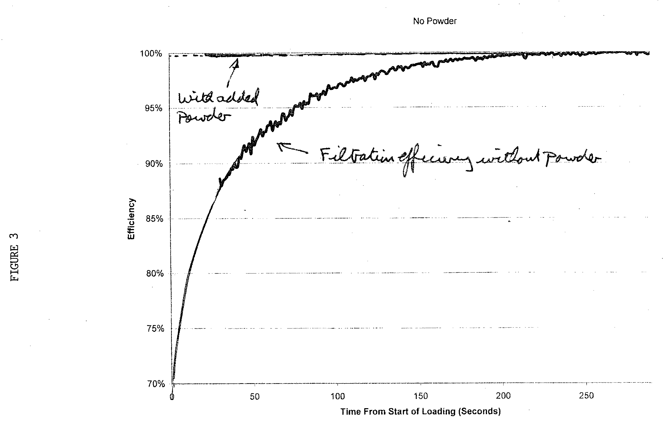
[0083]Dry powder zeolite (ZSM-5, 13 g) that was characterised by a Malvern Mastersizer 2000 as having an average particle size of about 2 μm in the form of an aqueous dispersion was distributed over the inlet side of the filter used in Example 1 after the trapped particulate matter in it had been completely removed by burning with air in an electric furnace maintained at 650° C. for 3 hours. The filter into which the inlet surface bridge network was to be introduced was disposed in the DPG device, which was run in fan only mode without fuel, i.e. without diesel particulate generation, so that a turbulent air flow entered the upstream side of the filter substrate. The zeolite was evenly dispersed over the inlet side of the filter by adding it through a 250 mesh sieve into the upstream turbulent air flow via a boss disposed in a housing of the conduit upstream of the filter so forming an aerosol that was carried in...
example 4
Filter Catalysed with Selective Catalytic Reduction Catalyst with Refractory Added Material
[0088]The same filter that was used in Comparative Example 3 was heated in an electric furnace at 650° C. to burn off all of the particulate matter and then when cooled zeolite (11 g ZSM-5) was evenly dispersed as an aerosol over the inlet side of the filter using the same method described in Example 2. The filtration performance and backpressure during loading with particulate matter were measured as previously and the results shown in FIGS. 7 and 8 respectively.
[0089]The filter was then fitted to the exhaust gas system of a bench-mounted Euro IV compliant, 2 litre direct injection, common rail engine (suitable e.g. for a passenger car) downstream of a 1 litre oxidation catalyst (95 g / ft3 with 2:1 weight ratio of platinum and palladium coated onto a 350 cell per square inch cordierite monolithic flow through substrate), with the filter orientated so that the powder treated channels were on th...
example 5
Filter Catalysed with Selective Catalytic Reduction Catalyst—with Added Catalysed Refractory Material
[0094]A filter with the same dimensions and SCR catalyst as in Comparative Example 3 was tested on the DPG and the filtration efficiency and backpressure performance was found to be similar to Comparative Example 3. The particulate matter was then completely removed by burning in an electric furnace at 650° C. and then when cooled a mixture of copper exchanged (2.5 wt % copper) chabazite zeolite (36 g) and zeolite ZSM5 (6 g) (no copper) was evenly dispersed as an aerosol over the inlet surface side of the filter using the same method described in Example 2.
[0095]The filtration efficiency and backpressure performance of the filter before and after the addition of the catalysed material are shown in FIGS. 11 and 12 respectively.
[0096]As well as achieving significant improvements in both filtration efficiency and backpressure the addition of catalysed material serves to increase the NOx...
PUM
| Property | Measurement | Unit |
|---|---|---|
| size | aaaaa | aaaaa |
| size | aaaaa | aaaaa |
| density | aaaaa | aaaaa |
Abstract
Description
Claims
Application Information
 - R&D
- Intellectual Property
- Life Sciences
- Materials
- Tech Scout
- Unparalleled Data Quality
- Higher Quality Content
- 60% Fewer Hallucinations
Browse by: Latest US Patents, China's latest patents, Technical Efficacy Thesaurus, Application Domain, Technology Topic, Popular Technical Reports.
© 2025 PatSnap. All rights reserved.Legal|Privacy policy|Modern Slavery Act Transparency Statement|Sitemap|About US| Contact US: help@patsnap.com


