Removable templates for directed self assembly

a self-assembly and template technology, applied in the direction of instruments, photomechanical treatment, electrical equipment, etc., can solve the problems of limited techniques and low throughpu

Active Publication Date: 2013-09-19
MASSACHUSETTS INST OF TECH
View PDF16 Cites 26 Cited by
  • Summary
  • Abstract
  • Description
  • Claims
  • Application Information

AI Technical Summary

Benefits of technology

[0005]According to an aspect, self-assembled BCP structures can be used as a functional pattern without interference from the physical templating features used to direct the patterns of the BCP.
[0008]According to embodiments, the final pattern may cover an entire area on which a pattern is to be transferred. The final pattern can be transferred to the underlying substrate without artifacts from the physical template used to direct the self-assembled pattern.

Problems solved by technology

However these techniques are limited by factors such as low throughput due to the serial patterning nature of SEBL or lower inherent resolutions limits of optical lithography, which require solutions to challenging physics problems such as finding appropriate low wavelength light sources (EUV) and material systems that can properly act as resists for such light sources.

Method used


Image

  • Removable templates for directed self assembly
  • Removable templates for directed self assembly
  • Removable templates for directed self assembly

Examples


example

Mesh Forming Cylinders

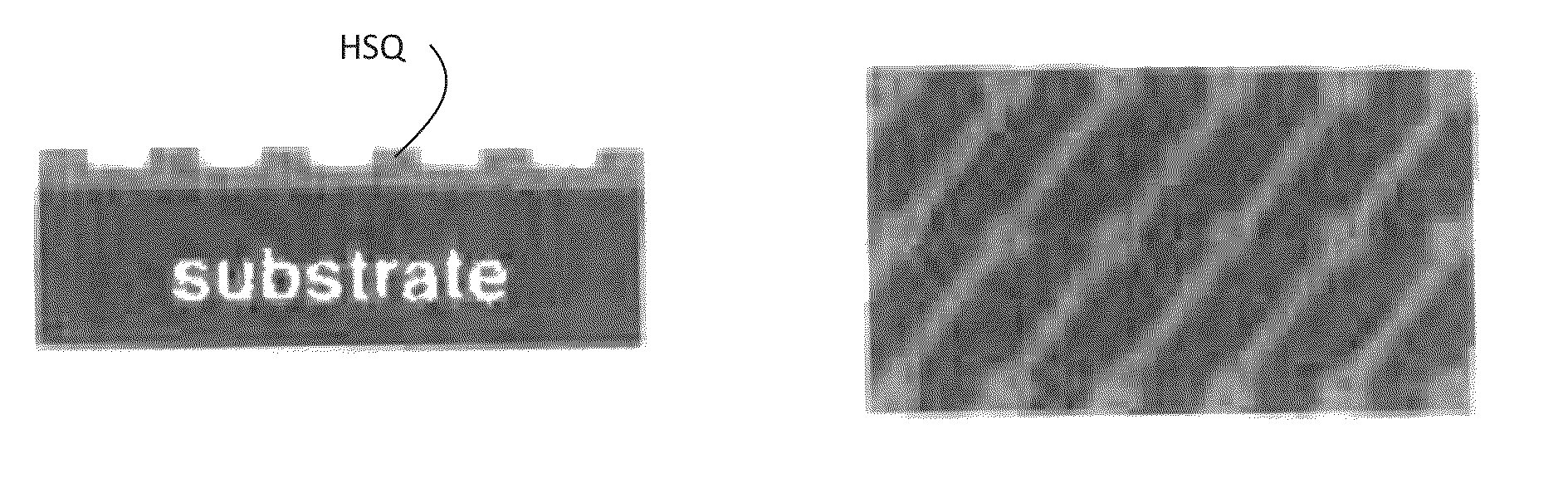
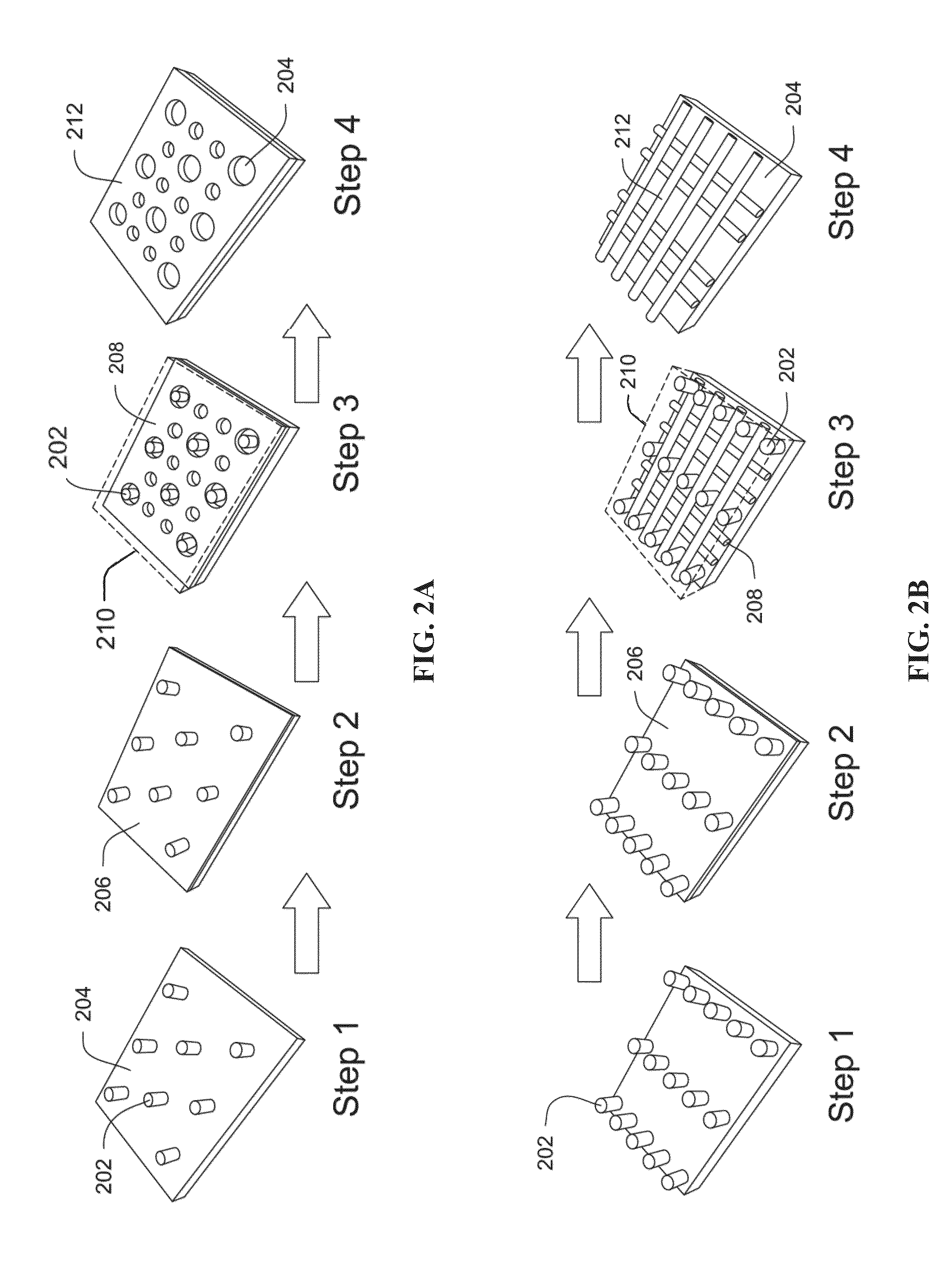
[0069]To illustrate the feasibility of 3-D structures (including the bilayer morphology shown in FIG. 2B), a templating process using HSQ was carried out and the results illustrated in the SEM images of an etched 3D-structure on a substrate found in FIGS. 6A-6D. It should be understood that this process can be carried out using sacrificial posts as well and additional examples are provided and described with respect to FIGS. 16A and 16B.

[0070]In particular, HSQ was spin coated at 40±2 nm thickness on Si (100) substrates. The post array templates were fabricated by means of electron-beam lithography of the HSQ resist at an acceleration voltage of 30 kV, beam current of 300 pA, and dot doses of 40 to 116 fC. After development and HSQ hardening by use of an oxygen plasma asher, the final post height was 33±2 nm. Next, the substrates and posts were chemically functionalized with hydroxyl terminated polystyrene (1 kg mol−1, 2 nm thick), which corresponds to the majo...

examples

Materials and Methods

Template Fabrication

[0092]Initial sacrificial post templates were fabricated using electron beam lithography (EBL) of 40 nm thick films of PMMA as a negative-tone resist as described with respect to FIGS. 2A and 2B (Step 1).

[0093]For the fabricated samples, prime silicon (100) wafers were cut into pieces ˜2 cm×2 cm and diluted PMMA was spin-coated onto the pieces. The PMMA (950 kg / mol in anisole) was diluted with a volumetric dilution ratio of about 1:8 PMMA:anisole. To produce 40 nm thickness films (measured by ellipsometer), a 4000 rpm spin coating speed was used. To evaporate the excess solvent and improve the adhesion between the PMMA resist and the substrate, the samples were baked on a hot plate at 200° C. for 2 min.

[0094]PMMA is typically a positive-tone resist; however PMMA can act as a negative-tone resist when exposed to doses of about 30 times the positive-tone dose and developed with methyl isobutyl ketone (MIBK) as part of a carbonization process. W...


PUM

PropertyMeasurementUnit
thicknessaaaaaaaaaa
heightaaaaaaaaaa
thickaaaaaaaaaa

Abstract

A sacrificial-post templating method is presented for directing block copolymer (BCP) self-assembly to form nanostructures of monolayers and bilayers of microdomains. The topographical post template can be removed after directing self-assembly and, therefore, is not incorporated into the final microdomain pattern. The sacrificial posts can be a material removable using a selective etchant that will not remove the material of the final pattern block(s). The sacrificial posts may be removable, at least in part, using a same etchant as for removing one of the blocks of the BCP, for example, a negative tone polymethylmethacrylate (PMMA) when a non-final pattern block of polystyrene is removed and polydimethylsiloxane (PDMS) remains on the substrate.

Description

[0001]This invention was made with government support under Contract No. 70NANB7H6168 awarded by the National Institute of Standards and Technology, and under Contract No. HR0011-10-3-0002 awarded by the Defense Advanced Research Projects Agency. The government has certain rights in the invention.BACKGROUND OF THE INVENTION[0002]Production of dense, defect-free and uniform nanopatterns over a large area is of significant concern for the semiconductor fabrication industry. State-of-the-art fabrication techniques include photolithography (immersion optical and interference lithography) and scanning electron-beam lithography (SEBL). However these techniques are limited by factors such as low throughput due to the serial patterning nature of SEBL or lower inherent resolutions limits of optical lithography, which require solutions to challenging physics problems such as finding appropriate low wavelength light sources (EUV) and material systems that can properly act as resists for such l...

Claims


Application Information

Patent Timeline
Patent Type & Authority Applications(United States)
IPC IPC(8): H01L21/308
CPCH01L21/3081H01L21/0271B81C2201/0149H01L21/31138B81C1/00031H01L21/31058G03F7/0002B81C1/00111B81C1/00428
Inventor GHARIEHALI, AMIR TAVAKKOLI KERMANINICAISE, SAMUEL MOSPENSBERGGREN, KARL K.GOTRIK, KEVIN WILLYROSS, CAROLINE A.
Owner MASSACHUSETTS INST OF TECH
Why Eureka
Try Eureka