Probe and object information acquisition apparatus using the same

a technology of object information and acquisition apparatus, applied in the direction of vibration measurement in solids, instruments, specific gravity measurement, etc., can solve the problems of solvent cracking, photoacoustic waves occurring as noise, stress applied to the support layer,

Active Publication Date: 2013-10-03
CANON KK
View PDF17 Cites 11 Cited by
  • Summary
  • Abstract
  • Description
  • Claims
  • Application Information

AI Technical Summary

Benefits of technology

[0038]Referring to FIG. 3, a photoacoustic probe of Example 2 according to the present invention will be described. In Example 2, the protection layer is formed using the spraying method. Example 2 has a configuration substantially equivalent to that of Example 1. In FIG. 3, components assigned with 300s having the last two digits identical to those of 200s illustrated in FIG. 2 indicate components having functions analogous to those illustrated in FIG. 2. In this example, the spraying method is employed as a method of forming a protection layer 305. The spraying method can form polyurethane into a film having a thickness of 10 μm or less. Such a method can also exert advantageous effects equivalent to those of Example 1.

Problems solved by technology

When light for causing photoacoustic waves enters the capacitive photoacoustic probe, photoacoustic waves occur as noise on the receiving surface of the probe.
However, in the case of using the probe that includes the vibration film and the support layer with the optical reflection layer stacked via the acoustic matching layer in the acoustic medium, stress is applied to the support layer and a solvent crack sometimes occurs.
Occurrence of the solvent crack, in turn, causes a crack on the support layer with the optical reflection layer.
Light enters through the crack to cause photoacoustic waves, thereby increasing noise.
Practically, not only the solvent, but also some chemical agents, such as oil and surfactants, exert analogous adverse effects.
Since the probe having the above configuration uses an adhesive for causing the vibration film to adhere to the support layer with the optical reflection layer, stress is unfortunately applied to the support layer.
However, a pinhole is sometimes formed.
Through use of the probe including the optical reflection layer with a pinhole or a scratch in the acoustic medium, the acoustic medium may penetrate into the support layer to which stress is applied, thereby causing a solvent crack.
Occurrence of the solvent crack widens the pinhole and scratch on the optical reflection layer, and increases the amount of transmission of light, which causes photoacoustic waves on the receiving surface of the probe.
Accordingly, noise may increase.

Method used


Image

  • Probe and object information acquisition apparatus using the same
  • Probe and object information acquisition apparatus using the same
  • Probe and object information acquisition apparatus using the same

Examples


example 1

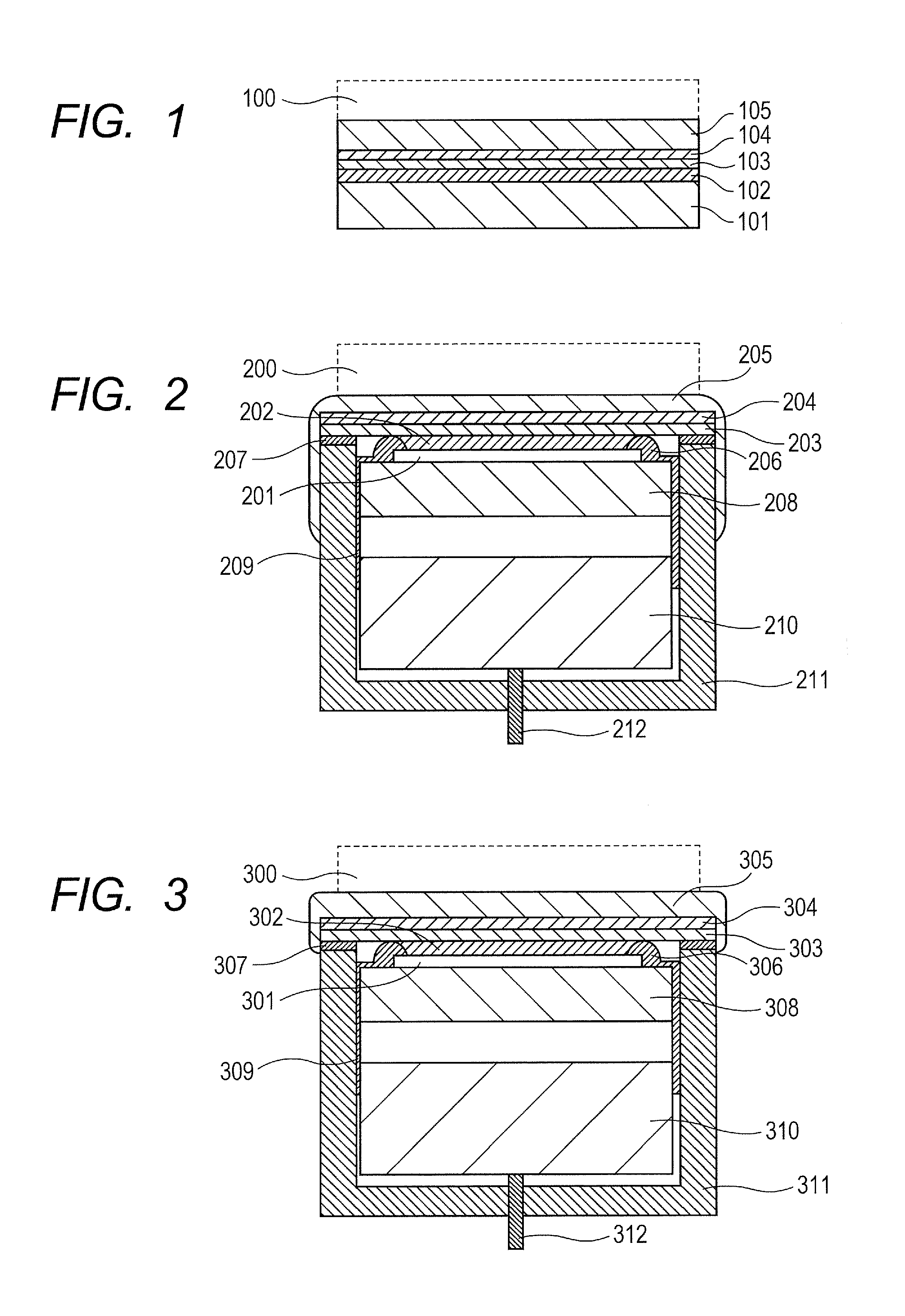
[0034]Referring to FIG. 2, the probe of Example 1 of the present invention will be described. In this example, the protection layer is formed of paraxylene resin (parylene). A probe substrate 201 includes: a receiving part including a membrane made of any of single crystal silicon and silicon nitride on a cavity formed on the single crystal silicon substrate; and electrodes. The probe substrate 201 is fixed to the device board 208, and electrically connected to a pad (not illustrated) on the device board 208 by wire bonding. Wires and the pad are protected by seal members 206. The receiving part, which receives photoacoustic waves, has dimensions of 30 mm×20 mm, and is formed between two seal members 206. A signal of receiving photoacoustic waves from the receiving part of the probe substrate 201 is connected to a circuit 210 through a flexible substrate 209. The signal having passed through the circuit 210 is connected to the signal processor (not illustrated) through a cable 212.

[...

example 2

[0038]Referring to FIG. 3, a photoacoustic probe of Example 2 according to the present invention will be described. In Example 2, the protection layer is formed using the spraying method. Example 2 has a configuration substantially equivalent to that of Example 1. In FIG. 3, components assigned with 300s having the last two digits identical to those of 200s illustrated in FIG. 2 indicate components having functions analogous to those illustrated in FIG. 2. In this example, the spraying method is employed as a method of forming a protection layer 305. The spraying method can form polyurethane into a film having a thickness of 10 μm or less. Such a method can also exert advantageous effects equivalent to those of Example 1.

example 3

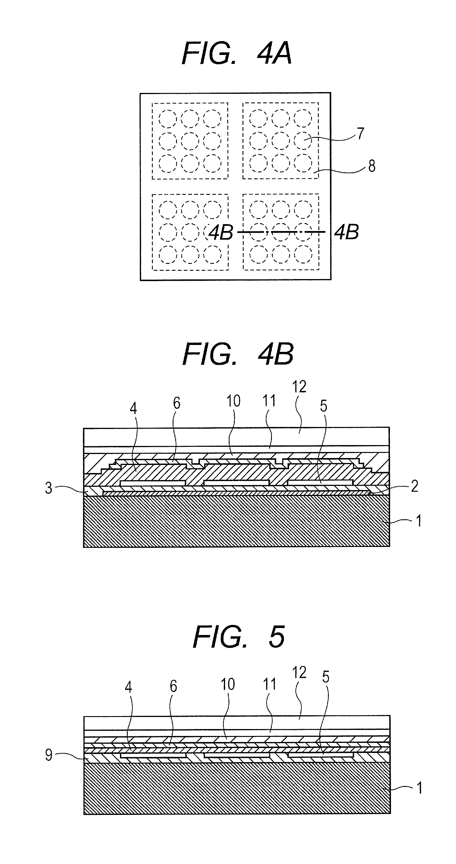
[0039]Referring to FIG. 6, a photoacoustic probe of Example 3 according to the present invention will be described. The probe of this example has a layer configuration on a vibration film as illustrated in FIG. 6. The probe has a configuration where a stress alleviation layer 402 having functions of stress alleviation and for acoustic conformity, a support layer 403, a gas barrier layer 404, an optical reflection layer 405 and a protection layer 406 are stacked on a photoacoustic probe substrate 401 including a receiving part. The stress alleviation layer 402 is formed of PDMS and has, for instance, an acoustic impedance of about 1.5 MRayls. The support layer 403 is made of polymethylpentene (TPX) and has, for instance, an acoustic impedance of about 1.8 MRayls. The gas barrier layer 404 is made of SiO2 and has a gas barrier property and moisture resistance. The optical reflection layer 405 is formed of Au / Cr. The gas barrier layer 404 and the optical reflection layer 405 are thin. ...


PUM

PropertyMeasurementUnit
thicknessaaaaaaaaaa
light transmittanceaaaaaaaaaa
thicknessaaaaaaaaaa

Abstract

A probe is provided in which penetration of an acoustic medium into a support layer of an optical reflection member through a pinhole or a scratch on an optical reflection layer is suppressed, occurrence of a solvent crack is suppressed, and noise due to photoacoustic waves that occurs on a receiving surface can be suppressed. The probe includes an element having at least one cell in which a vibration film containing one electrode out of two electrodes that are provided so as to interpose a space therebetween is vibratably supported. The probe further includes a support layer disposed on the vibration film, and an optical reflection layer disposed on the support layer. A protection layer against an acoustic medium is formed on the optical reflection layer.

Description

BACKGROUND OF THE INVENTION[0001]1. Field of the Invention[0002]The present invention relates to a probe that is used as a photoacoustic probe for receiving photoacoustic waves caused by an object owing to light with which the object is irradiated and includes a capacitive electromechanical transducer, and an object information acquisition apparatus using the same.[0003]2. Description of the Related Art[0004]Conventionally, ultrasonic probes employing transducers made of piezoelectric material (i.e., electromechanical transducers) have been used. In recent years, capacitive micromachined ultrasonic transducers (CMUT) manufactured using a semiconductor process have been attracting attention. For instance, the capacitive micromachined ultrasonic transducer has cells each including two parallel plane electrodes and a cavity, and can send and receive acoustic waves by allowing a vibration film (membrane), which is on one side and can vibrate, to vibrate. Particularly in an acoustic medi...

Claims


Application Information

Patent Timeline
Patent Type & Authority Applications(United States)
IPC IPC(8): G01N29/00
CPCG01N29/2418G01N29/00G01N21/1702
Inventor WATANABE, SHINICHIROKANDORI, ATSUSHITORASHIMA, KAZUTOSHI
Owner CANON KK
Why Eureka
Try Eureka