Dual Fuel Engine System And Method Of Operating

a fuel engine and dual fuel technology, applied in the direction of engine ignition, electric ignition installation, electrical control, etc., can solve the problems of high particulate emissions, incomplete combustion of diesel fuel, and low oxide nitrogen (nox) and particulate emission levels of compression-ignited engines and diesel engines in particular. to achieve the effect of maximizing the use of gaseous fuel

Active Publication Date: 2013-10-03
WESTPORT
View PDF3 Cites 33 Cited by
  • Summary
  • Abstract
  • Description
  • Claims
  • Application Information

AI Technical Summary

Benefits of technology

[0050]In the present dual fuel engine system, the control system adapts the operation of the engine from combustion cycle to combustion cycle, which allows substantially instantaneous adaptation to different grades of gaseous fuel irrespective of whether the current engine operation is transient or not.
[0051]The present dual fuel engine system reduces emissions of CO2, NOx and particulates, such as soot, from the engine by allowing the vehicle/en

Problems solved by technology

However, compression-ignited engines and diesel engines in particular typically cannot achieve the low oxides of nitrogen (NOx) and particulate emission levels that are possible with spark-ignited engines.
This can result in incomplete combustion of the diesel fuel, which tends to result in high particulate emissions.
Furthermore, the fuel-rich equivalence ratio can also lead to high flame temperatures in the combustion process, which results in increased NOx emissions.
One solution is to reduce the amount of diesel injected into the combustion chamber, which reduces the equivalence ratio and works to reduce particulate and NOx emissions; however, it also reduces engine power.
Utilization of such gaseous fuels with diesel engines not only provides for more complete combustion and thereby enhanced fuel economy, but also typically results in lower engine emissions.
However, gaseous fuels typically do not have the cetane value required to allow for their ignition through compression.
Accordingly, these systems are typically expensive and oftentimes unreliable.
Dual-fuel systems have suffered a number of disadvantages that have prevented widespread use of such systems.
The first disadvantage is typically encountered at high load operating conditions when elevated temperature and pressure in the engine during the compression strokes makes the intake air/gaseous f

Method used


Image

  • Dual Fuel Engine System And Method Of Operating
  • Dual Fuel Engine System And Method Of Operating
  • Dual Fuel Engine System And Method Of Operating

Examples


Embodiment Construction

)

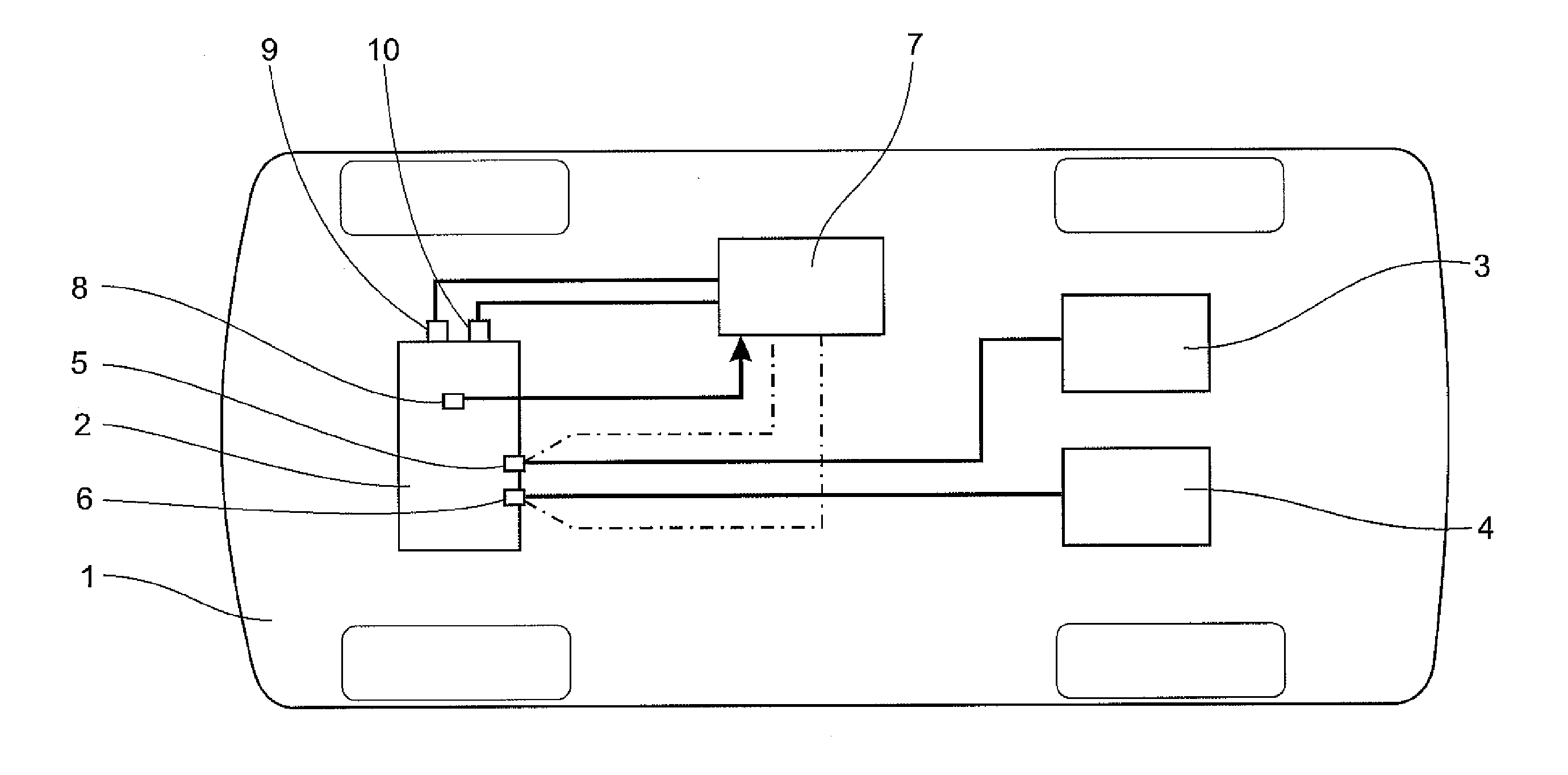
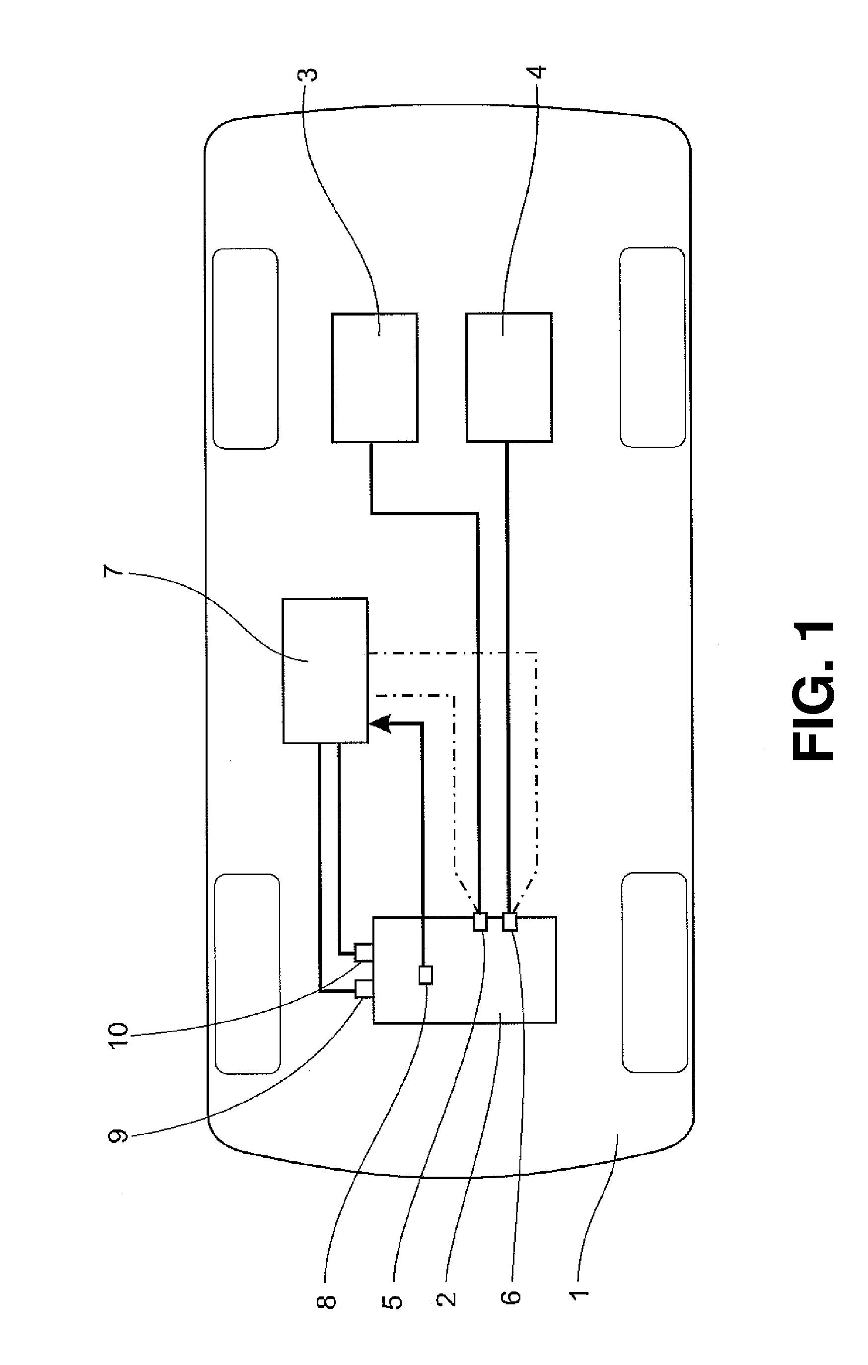
[0055]FIG. 1 schematically illustrates a vehicle 1 provided with a dual fuel engine 2. Dual fuel engine 2 is operable on a gaseous fuel drawn from a first tank 3 and on a compression ignitable liquid fuel drawn from a second tank 4. Engine 2 comprises at least one combustion chamber (not shown), which is supplied with gaseous fuel controlled by a first valve 5, in the form of a first controllable injector, connected to first tank 3. Each combustion chamber is further supplied with liquid fuel controlled by a second valve 6, in the form of a second controllable injector, connected to second tank 4. First controllable injector 5 can be placed in an air intake conduit of the combustion chamber, while second controllable injector 6 can be arranged to inject fuel directly into the combustion chamber. Alternatively, the first and second controllable injectors can be combined into a common dual fuel injector, preferably but not necessarily arranged to inject fuel directly into the combust...


PUM


Abstract

A dual fuel engine operates on a gaseous fuel and a liquid fuel. The engine comprises a supply of gaseous fuel controlled by a first valve, a supply of compression ignitable liquid fuel controlled by a second valve, a control unit for controlling the supply of gaseous fuel and liquid fuel to each combustion chamber in the engine, and at least one knock sensor arranged to detect knock in each combustion chamber and to transmit an output signal proportional to the detected level of knock to the control unit. If knock is detected, the amount of gaseous fuel injected will be reduced while the amount of liquid fuel will be increased. The engine control system will subsequently adapt to the lower grade fuel and perform a calibration to operate as close as possible to the knock limit for the particular fuel.

Description

CROSS-REFERENCE TO RELATED APPLICATION(S)[0001]This application is a continuation of International Application No. PCT / SE2011 / 051283 having an international filing date of Oct. 27, 2011, entitled “Dual Fuel Engine System”. The '283 international application claimed priority benefits, in turn, from Swedish Patent Application No. 1051135-0 filed on Oct. 29, 2010. The '283 international application is hereby incorporated by reference herein in its entirety.FIELD OF THE INVENTION[0002]The present invention relates generally to dual fuel engine systems. More particularly, the present invention relates to an injection system for controlling the injection of a gaseous fuel into an air intake of a diesel engine.BACKGROUND OF THE INVENTION[0003]Due to the high thermal efficiency achieved by compression-ignited engines (for example, in comparison with spark-ignited engines), these engines are commonly utilized in industrial applications. The high efficiency of compression-ignited engines, suc...

Claims


Application Information

Patent Timeline
IPC IPC(8): F02D43/04
CPCF02B69/04F02D19/0647F02D19/081F02D19/10F02D35/027F02D41/0027F02D43/04F02D41/2451Y02T10/36F02D19/0636F02D19/0644F02D19/0652F02D19/066F02D41/2438Y02T10/30
Inventor MOREN, MATSJOHANSSON, ANDERS
Owner WESTPORT
Why Eureka
Try Eureka