Mass Spectrometer With Beam Expander

a mass spectrometer and beam expander technology, which is applied in the field of mass spectrometers with beam expanders, can solve the problems of reducing the overall resolution of the mass analyser, the practical limit of the known approach for the extraction time of flight mass analyser, and the impracticality of increasing the ratio vp/lp beyond a certain limit, so as to reduce the turnaround time of ions and achieve high resolution the effect of flight tim

Inactive Publication Date: 2013-10-03
MICROMASS UK LTD
View PDF4 Cites 23 Cited by
  • Summary
  • Abstract
  • Description
  • Claims
  • Application Information

AI Technical Summary

Benefits of technology

[0057]expanding an ion beam upstream of a Time of Flight mass analyser so as to reduce the turnaround time of ions in the ion beam which are orthogonally accelerated into the Time of Flight mass analyser.
[0058]According to the preferred embodiment a mass spectrometer is provided comprising a RF ion confinement device, an ion beam expander and a Time of Flight mass analyser. The beam expander preferably comprises one or more lenses which preferably expand an ion beam to such a size that a practical two stage Wiley McLaren Time of Flight mass analyser can be realised without suffering from an excessively large turnaround time aberration. As a result, at least according to the preferred embodiment a high resolution Time of Flight mass analyser can be provided which does not require the provision of a reflectron.

Problems solved by technology

Turnaround time is often the major limiting aberration in designing a Time of Flight mass spectrometer and instrument designers go to great lengths to attempt to minimise this effect which results in a reduction in the overall resolution of the mass analyser.
However, the known approach has a practical limit for a two stage extraction Time of Flight mass analyser since Wiley McLaren type spatial focussing necessitates that the Time of Flight mass analyser has a short field free region L3.
This is highly problematic since it requires very fast, high bandwidth detection systems and hence it is impractical to increase the ratio Vp / Lp beyond a certain limit.
However, the addition of a reflectron to a Time of Flight mass spectrometer adds complexity and expense to the overall design of the instrument.

Method used


Image

  • Mass Spectrometer With Beam Expander
  • Mass Spectrometer With Beam Expander
  • Mass Spectrometer With Beam Expander

Examples


Embodiment Construction

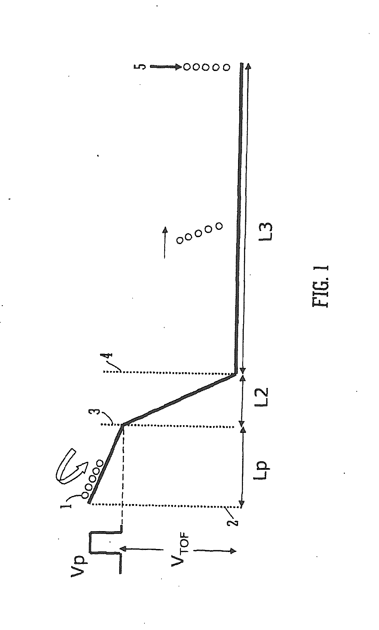
[0084]A preferred embodiment of the present invention will now be described initially by referring back to Eqn. 1. If Eqn. 1 is rewritten in terms of velocity vo then this leads to the relationship for the turnaround time t′ such that:

t′=Lp·mvqVp(4)

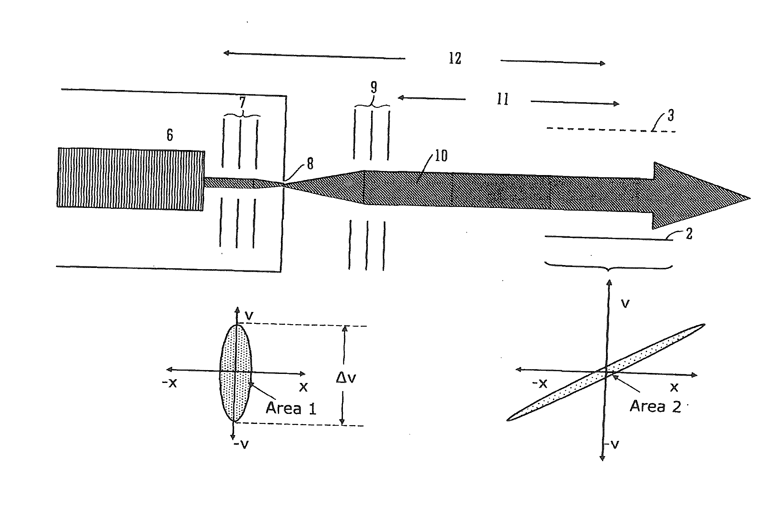
[0085]The term my is the momentum of an ion beam and the width Lp of the pusher region is inherently related linearly to the extent or width of the ion beam in the pusher or extraction region of the Time of Flight mass analyser.

[0086]A fundamental theorem in ion optics is “Liouville's theorem” which states that “For a cloud of moving particles, the particle density p(x, px, y, py, z, pz) in phase space is invariable” (Geometrical Charged-Particle Optics, Harald H. Rose, Springer Series in Optical Sciences 142), wherein px, py and pz are the momenta of the three Cartesian coordinate directions.

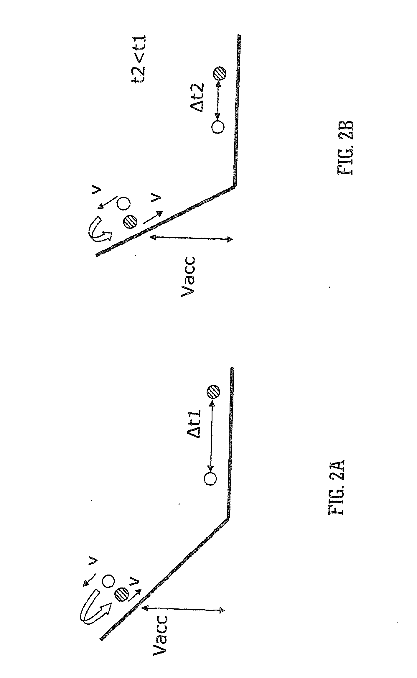
[0087]According to Liouville's theorem, a cloud of particles at a time t1 that fills a certain volume in phase space may change its shape at a later...


PUM


Abstract

A mass spectrometer is disclosed comprising a RF confinement device, a beam expander and a Time of Flight mass analyser. The beam expander is arranged to expand an ion beam emerging from the RF confinement device so that the ion beam is expanded to a diameter of at least 3 mm in the orthogonal acceleration extraction region of the Time of Flight mass analyser.

Description

CROSS REFERENCE TO RELATED APPLICATIONS[0001]This application claims priority from and the benefit of United Kingdom Patent Application No. 1009596.6 filed on 8 Jun. 2010, U.S. Provisional Patent Application Ser. No. 61 / 354,736 filed on 15 Jun. 2010, United Kingdom Patent Application No. 1010300.0 filed on 18 Jun. 2010 and U.S. Provisional Patent Application Ser. No. 61 / 359,562 filed on 29 Jun. 2010. The entire contents of these applications are incorporated herein by reference.[0002]The present invention relates to a mass spectrometer and a method of mass spectrometry.BACKGROUND TO THE INVENTION[0003]Two stage extraction Time of Flight mass spectrometers are well known. The basic equations that describe two stage extraction Time of Flight mass spectrometers were first set out by Wiley and McLaren (W. C. Wiley and I. H. McLaren “Time-of-Flight Mass Spectrometer with Improved Resolution”, Review of Scientific Instruments 26, 1150 (1955)). The principles apply equally to continuous ax...

Claims


Application Information

Patent Timeline
Patent Type & Authority Applications(United States)
IPC IPC(8): H01J49/40
CPCH01J49/0095H01J49/062H01J49/401H01J49/067H01J49/0031H01J49/405
Inventor BROWN, JEFFERY MARKGILBERT, ANTHONY JAMESHOYES, JOHN BRIANLANGRIDGE, DAVID J.WILDGOOSE, JASON LEE
Owner MICROMASS UK LTD
Why Eureka
Try Eureka