
Target for x-ray generator, method of manufacturing the same and x-ray generator

Active Publication Date: 2013-10-03
RIGAKU CORP
View PDF6 Cites 30 Cited by
  • Summary
  • Abstract
  • Description
  • Claims
  • Application Information

AI Technical Summary

Benefits of technology

The invention relates to an apparatus for supplying power to an X-ray focus using a thin film target. The target is placed on a diamond plate which is air-tightly connected to a holder made of electrically conductive material. The thin film target is connected to the holder through its outer edge, while the thin film is in direct contact with a refrigerant for better cooling. The holder is designed to be flexible and deformable without damaging the diamond plate, which prevents the need for expensive and difficult-to-deal with crystal substrates. The apparatus helps to generate a stronger X-ray with minimal heat production.

Problems solved by technology

Therefore, in a case that a small cylindrical target is formed inside the diamond substrate, as described in the patent document 1, a problem of damage to the target may occur because of an inadequate connection of the target to a power supply.
Further, even if the diamond plate with a thin film target formed thereon, is fixed to a conventional target fixing material based on a conventional target supporting method, because there is a large difference in thermal expansion coefficient between the diamond plate and a fixing material, and a temperature is raised, it involves a problem that a stable joint of the diamond plate and the target material is difficult as the X-ray target having a large temperature gradient.
Regarding a system of forming a thin film target on a diamond substrate, some of the documents seem to be at an experimental level yet, due to the above-mentioned difficulty, and almost no practicable technique that can be employed as a commercial product is proposed at present.

Method used


Image

  • Target for x-ray generator, method of manufacturing the same and x-ray generator
  • Target for x-ray generator, method of manufacturing the same and x-ray generator
  • Target for x-ray generator, method of manufacturing the same and x-ray generator

Examples


first embodiment

[0042](A target for an X-ray generator )

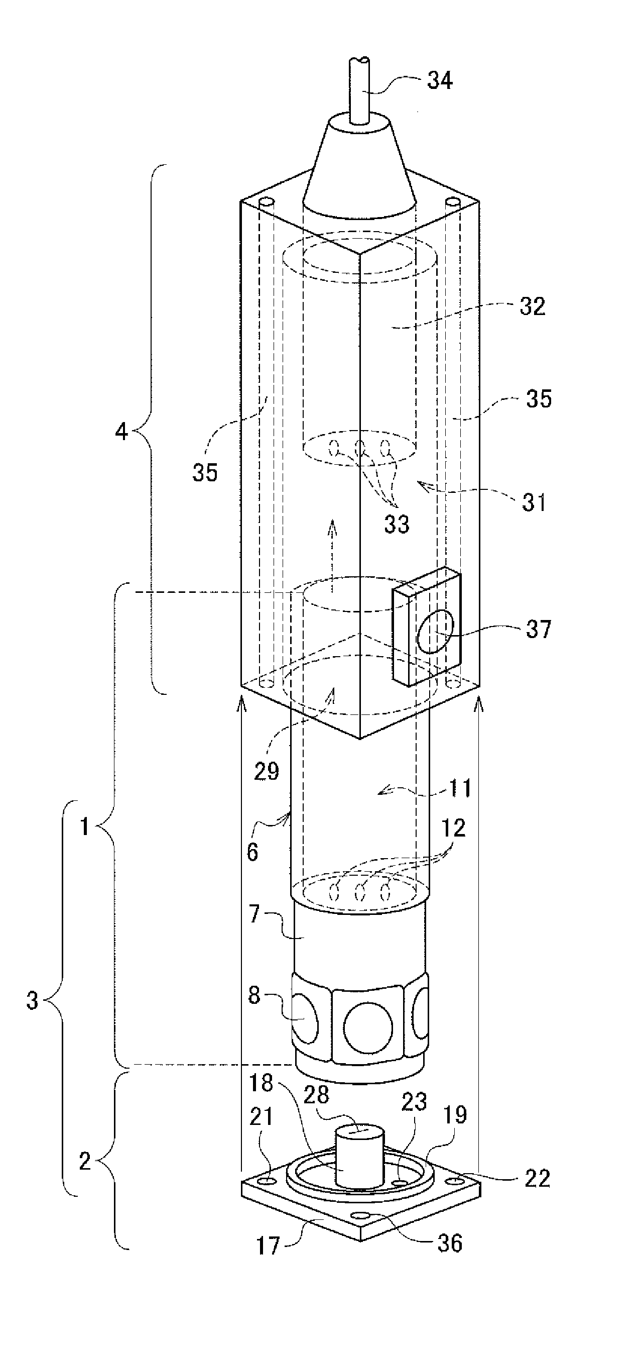
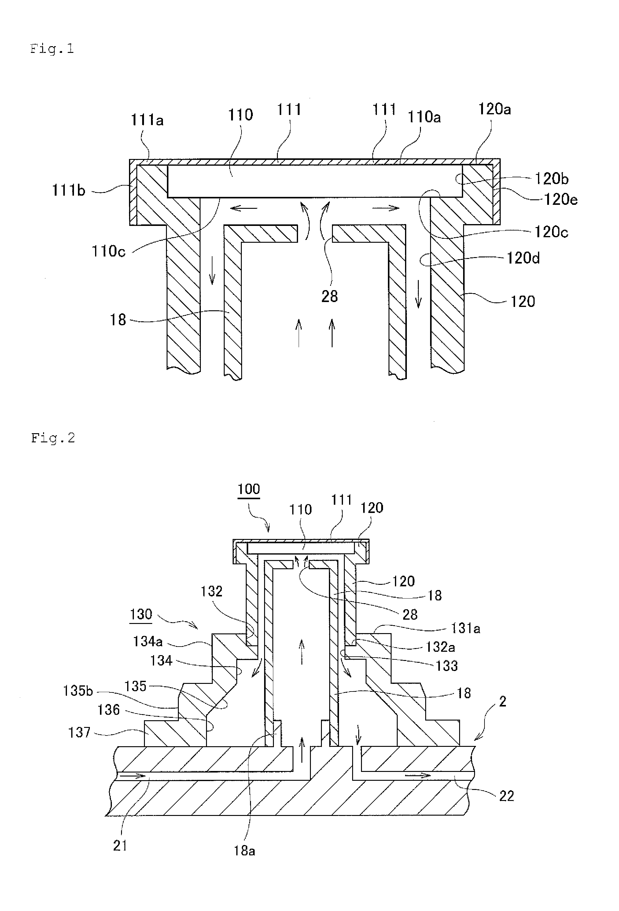
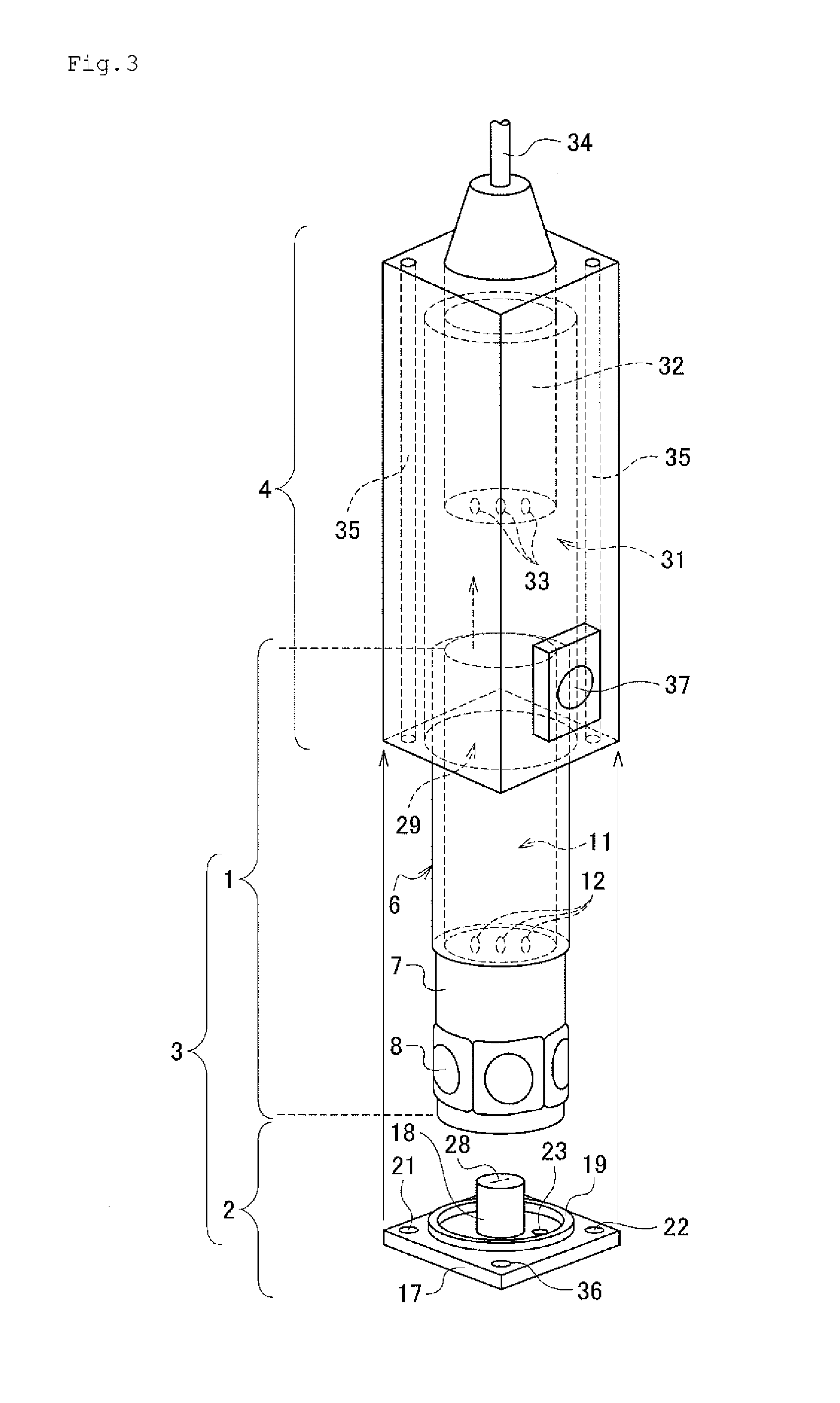
[0043]FIG. 1 is an enlarged partial cross sectional view showing the target for an X-ray generator according to the first embodiment of the present invention. FIG. 2 is a cross sectional view showing the target for an X-ray generator according to the first embodiment of the present invention. FIG. 3 is a schematic view showing the X-ray generator according to the first embodiment of the present invention, in an exploded state. FIG. 4 is a cross sectional view of the X-ray generator shown in FIG. 3. Hereinafter, the target for an X-ray generator, the method of manufacturing the target for an X-ray generator, and the X-ray generator according to the embodiments of the present invention will be described with reference to the attached drawings.

[0044]Referring to FIGS. 1 and 2, a target 100 for an X-ray generator comprises a diamond plate 110 formed into a shape of a circular plate which is air-tightly joined to a holder part 120 formed in a cylin...

second embodiment

[0075](A target for an X-ray generator )

[0076]FIG. 6 is a partially enlarged cross sectional view of the target for an X-ray generator according to the second embodiment of the present invention. As shown in FIG. 6, configuration of this embodiment is the same with the first embodiment, except that an base film 112 of Cr film having a thickness of about 10 nm is formed onto the surface of the diamond plate 110, a thin film target 111 similar to that of the first embodiment is formed thereon, and furthermore, another base film 114 is formed onto the backside 110c of the diamond plate 110, and a corrosion resistant film 113 is formed thereon. The base film 114 is a Cr film having a thickness of about 10 nm, and the corrosion resistant film 113 is an Au film having a thickness of 10 μm.

[0077]Besides, the base film 112 formed between the thin film target 111 and the diamond plate 110 has a thickness selected appropriately to be in a range of 1 nm to 40 nm, and uses a material of either ...


PUM

PropertyMeasurementUnit
Thicknessaaaaaaaaaa
Thicknessaaaaaaaaaa
Thicknessaaaaaaaaaa

Abstract

There is provided a target for an X-ray generator, including: a holder part made of an electrically conductive material and having an opening part; a diamond plate air-tightly joined to the holder part so as to close the opening part; a thin film target provided on a surface of the diamond plate, with its outer peripheral part extending to the holder part to be electrically connected to the holder part, wherein the holder part is configured to be electrically connected to a power supply of the X-ray generator, and the diamond plate is incorporated into the X-ray generator with one side disposed in a vacuum atmosphere where the thin film target is formed, and an opposite side thereto disposed at a side where the diamond plate is brought into thermal contact with a refrigerant and cooled.

Description

BACKGROUND[0001]1. Field of the Invention[0002]The present invention relates to a target for an X-ray generator which is particularly used for generating a high brilliance (intensity) X-ray, a method of manufacturing the same and the X-ray generator.[0003]2. Description of the Related Art[0004]There is a generally known X-ray generator, such as an apparatus using a filament as a cathode and using a target as an anode, wherein the filament is available as a thermal electron source and the target is an object with which electrons collide. A high voltage of several tens of kilo volts is applied between these cathode and anode so that fast electrons collide with the target, to thereby generate an X-ray.[0005]A brilliance level (called X-ray intensity hereafter) capable of generating X-ray, can be given as a most basic performance of the X-ray generator, and various attempts have been made conventionally for increasing the X-ray intensity. In many cases, a value obtained by dividing an a...

Claims


Application Information

Patent Timeline
IPC IPC(8): H01J35/12
CPCH01J35/12H01J2235/081H01J2235/083H01J35/32H05G1/025H05G1/02H01J35/105H01J35/108A61B6/4488H01J35/13
Inventor OMOTE, KAZUHIKOSHIMIZU, KAZUAKIOSAKA, NAOHISA
Owner RIGAKU CORP
Learn More