Device for controlling a hydraulic accumulator of a hydraulic system

Inactive Publication Date: 2013-10-10
ROBERT BOSCH GMBH
View PDF2 Cites 10 Cited by
  • Summary
  • Abstract
  • Description
  • Claims
  • Application Information

AI Technical Summary

Benefits of technology

[0035]The valve main stage may be further improved if a damping spring or an element having corresponding damping material properties (damping member) is situated between the guiding section and the valve body. An axial damping action may thus be easily provided, whereby the function of the valve main stage may be improved, the operating noise may be reduced and t

Problems solved by technology

The latter is provided by a mechanical pump (i.e., one driven by the internal combustion engine), the pump generally having an overdimensioned design due to the linear dependency of the volumetric flow on the rotational speed and due to reserves provided for taking into account the idling speed of the internal combustion engine and a possibly high oil temperature.
When the internal combustion machine is stopped during the stopping phase, and when the hydraulic pump is stopped, the transmission may no longer be supplied with sufficient pressure or

Method used


Image

  • Device for controlling a hydraulic accumulator of a hydraulic system
  • Device for controlling a hydraulic accumulator of a hydraulic system
  • Device for controlling a hydraulic accumulator of a hydraulic system

Examples


Embodiment Construction

[0064]The same reference numerals are used for functionally equivalent elements and variables in all figures, even in different exemplary embodiments. In many of the modified exemplary embodiments explained, only the essential differences from the preceding exemplary embodiment or the preceding exemplary embodiments are discussed in the description of the function.

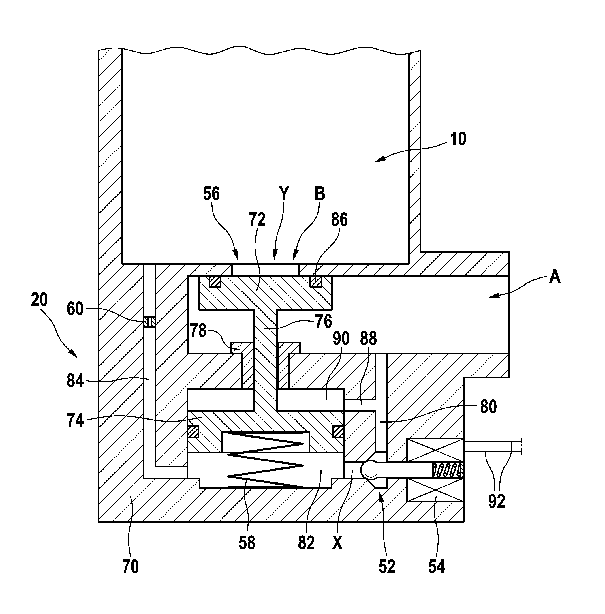
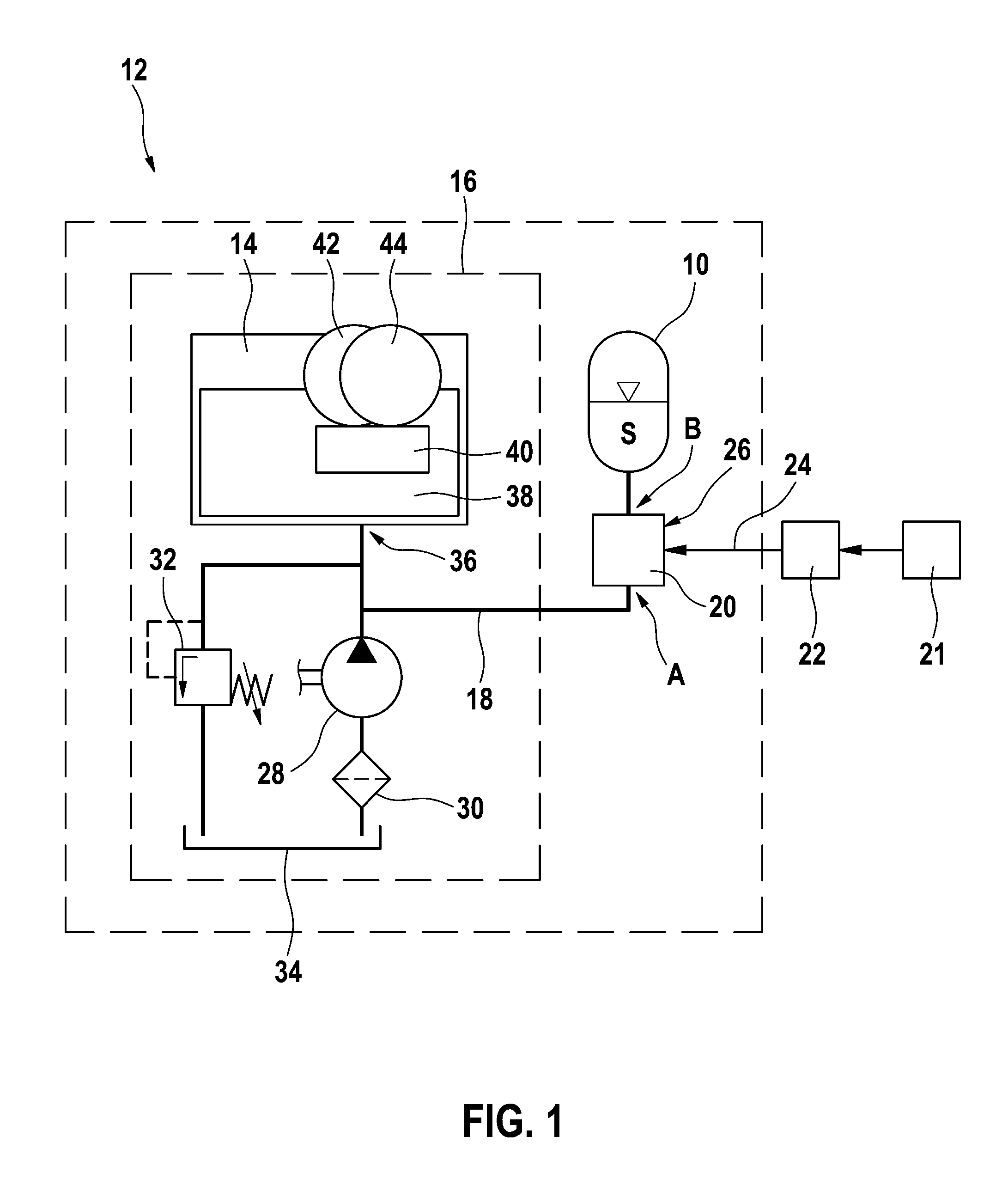
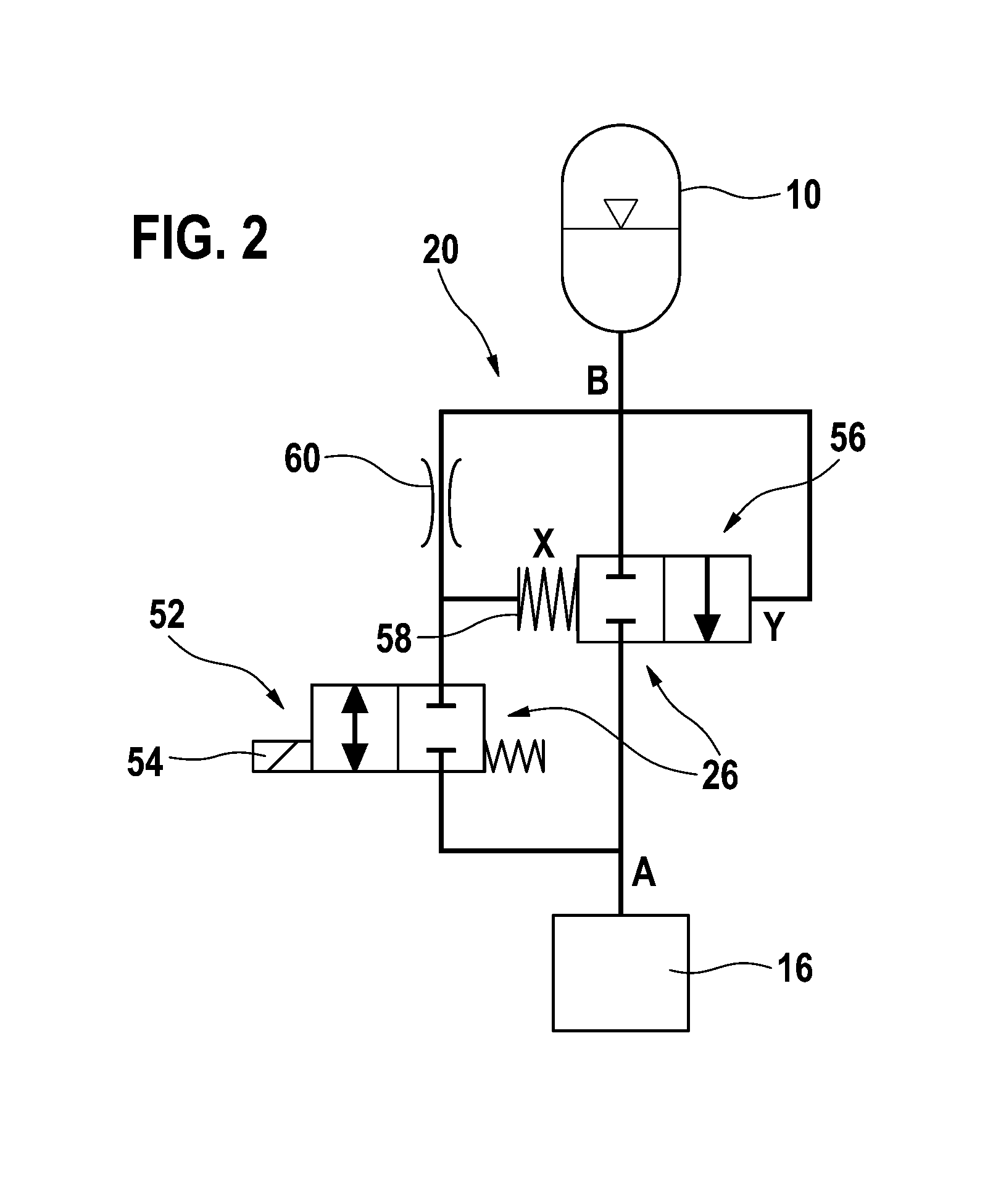
[0065]FIG. 1 shows a simplified schematic representation of a configuration of a hydraulic accumulator 10 in a hydraulic system 12 of an automatic transmission 14 of a motor vehicle, which is not illustrated in further detail herein. Hydraulic accumulator 10, which in the present case is a pressure accumulator 10, is connected to remaining hydraulic system 16 via a hydraulic connection 18 with the aid of a device 20 which is explained in greater detail below. Device 20 includes a valve device 26 which is electromagnetically actuatable by a first control and / or regulating device 21 of the motor vehicle with the aid of an ou...


PUM


Abstract

A device is described for controlling a hydraulic accumulator of a hydraulic system, for example a vehicle transmission, having a valve device which may connect and disconnect an accumulator-side port of the device to and from a system-side port, the valve device including at least one valve main stage, which is situated hydraulically between the accumulator-side port and the system-side port and to which a pressure prevailing hydraulically at the accumulator-side port is preferably applied by an application means in the opening direction, the valve device also including an electrically actuated control valve which may connect the system-side port to a control port of the valve main stage which acts in the closing direction of the valve main stage and to the accumulator-side port, at least one first throttle being situated between the control valve and the accumulator-side port.

Description

CROSS REFERENCE TO RELATED APPLICATIONS[0001]The present application is the national stage entry of International Patent Application No. PCT / EP2011 / 065543, filed on Sep. 8, 2011, which claims priority to Application No. DE 10 2010 042 194.4, filed in the Federal Republic of Germany on Oct. 8, 2010.FIELD OF INVENTION[0002]The present invention relates to a device for controlling a hydraulic accumulator of a hydraulic system.BACKGROUND INFORMATION[0003]So-called start-stop functions for motor vehicles are known from the market, with the aid of which the internal combustion engine may be automatically turned off by a control unit when the vehicle is at a standstill. This may help save fuel in a range from approximately 3% to approximately 5%.[0004]Automatic transmissions, for example a stepped transmission, a dual-clutch transmission or continuously variable transmission, are generally activated hydraulically and require a hydraulic pressure and a hydraulic volumetric flow for operatio...

Claims


Application Information

Patent Timeline
IPC IPC(8): F15B1/027
CPCF15B1/027F15B13/0431F16H61/0025F16H61/0009F16H2061/0034F15B2201/411F15B1/033Y10T137/86485
Inventor BLOCK, RUEDIGERSTEINBACH, NILSRUDOLPH, WOLFGANGHESS, WERNERKRASTEV, IANISLAVSTACHELY, MANFREDSCHNEIDER, HELMUTSTRAUSS, STEFFENKULOW, UWEOTT, CHRISTOF
Owner ROBERT BOSCH GMBH
Why Eureka
Try Eureka