Coaptation enhancement implant, system, and method

a technology of coaptation and implant, applied in the field of improved medical devices, systems and methods, can solve the problems of decreased blood flow, increased risk of cardiac failure, and increased risk of cardiac failure, and achieve the effect of reducing mal-coaptation and improving valve function

Active Publication Date: 2012-08-02
POLARES MEDICAL INC
View PDF2 Cites 193 Cited by
  • Summary
  • Abstract
  • Description
  • Claims
  • Application Information

AI Technical Summary

Benefits of technology

[0039]Advantageously, the devices and systems described herein can allow a physician to determine an effectiveness of the implant at mitigating the mal-coaptation while a delivery catheter remains coupled to at least one of the anchors and / or to the coaptation assist body. The catheter may remain coupled to the anchors such that the catheter system does not impose a significant load on the implant, such that the implant can be evaluated for effectiveness in substantially the position and configuration the implant will have once the catheter system is decoupled and removed. If the desired results are not seen, the physician can move and / or replace the coupled anchor, and / or can replace the coaptation assist body while leaving at least another of the anchors deployed. While some exemplary anchor embodiments use a tissue penetrating helical body having a helical axis configured for rotating the helical body about the helical axis so that helical body penetrates the first target location from within the heart, a variety of alternative anchors might be used. In some embodiments, the anchors might comprise suture, clips, staples, radiofrequency energy welds, or the like, and may be used to mount the body to heart tissue within the heart in an open surgical approach, during a robotic or endoscopic procedure, with access to the valve optionally being provided through a puncture or incision through the ventricular apex or atrial appendage, or the like. The implant will typically be configured so that, when deployed, loads transmitted between the coaptation assist body and tissue of the heart allow the annulus of the heart valve to change in diameter by more than 10% with each beat of the heart. Despite these significant size excursions, and despite the first and second anchors being circumferentially separated around the annulus, the anchors may each support the deployed implant sufficiently independently of the other to inhibit subjecting any resilient (including super-elastic) anchor-anchor interconnecting structure to fatigue-related failure during long-term implantation. Hence, the invention can be used as a mitral leaflet coaptation enhancement device configured to be positioned within the mitral valve during a brief, minimally invasive procedure, and can improve valve function without requiring re-shaping of all or part of the mitral annulus, and without changing leaflet edge anatomy (such as by fusing leaflet edges or the like).

Problems solved by technology

Unfortunately, the AV valves may become damaged or may otherwise fail to function properly, resulting in improper closing.
Heart valve regurgitation can have serious consequences to a patient, often resulting in cardiac failure, decreased blood flow, lower blood pressure, and / or a diminished flow of oxygen to the tissues of the body.
Mitral regurgitation can also cause blood to flow back from the left atrium to the pulmonary veins, causing congestion.
Severe valvular regurgitation, if untreated, can result in permanent disability or death.
A variety of therapies have been applied for treatment of mitral valve regurgitation, and still other therapies may have been proposed but not yet actually used to treat patients.
However, medications can suffer from lack of patient compliance.
A significant number of patients may occasionally (or even regularly) fail to take medications, despite the potential seriousness of chronic and / or progressively deteriorating mitral valve regurgitation.
Pharmacological therapies of mitral valve regurgitation may also be inconvenient, are often ineffective (especially as the condition worsens), and can be associated with significant side effects (such as low blood pressure).
Regardless, open mitral valve surgery is generally a very invasive treatment carried out with the patient under general anesthesia while on a heart-lung machine and with the chest cut open.
Complications can be common, and in light of the morbidity (and potentially mortality) of open-heart surgery, the timing becomes a challenge—sicker patients may be in greater need of the surgery, but less able to withstand the surgery.
Procedures that are done with robots or through endoscopes are often still quite invasive, and can also be time consuming, expensive, and in at least some cases, quite dependent on the surgeon's skill.
While these various approaches and tools have met with differing levels of acceptance, none has yet gained widespread recognition as an ideal therapy for most or all patients suffering from mitral valve regurgitation.
Unfortunately, sealing between the native leaflets and the full perimeter of a balloon or other coaxial body may prove challenging, while the significant contraction around the native valve annulus during each heart beat may result in significant fatigue failure issues during long-term implantation if a buttress or anchor interconnecting cross member is allowed to flex.
Moreover, the significant movement of the tissues of the valve may make accurate positioning of the implant challenging regardless of whether the implant is rigid or flexible.

Method used


Image

  • Coaptation enhancement implant, system, and method
  • Coaptation enhancement implant, system, and method
  • Coaptation enhancement implant, system, and method

Examples


Embodiment Construction

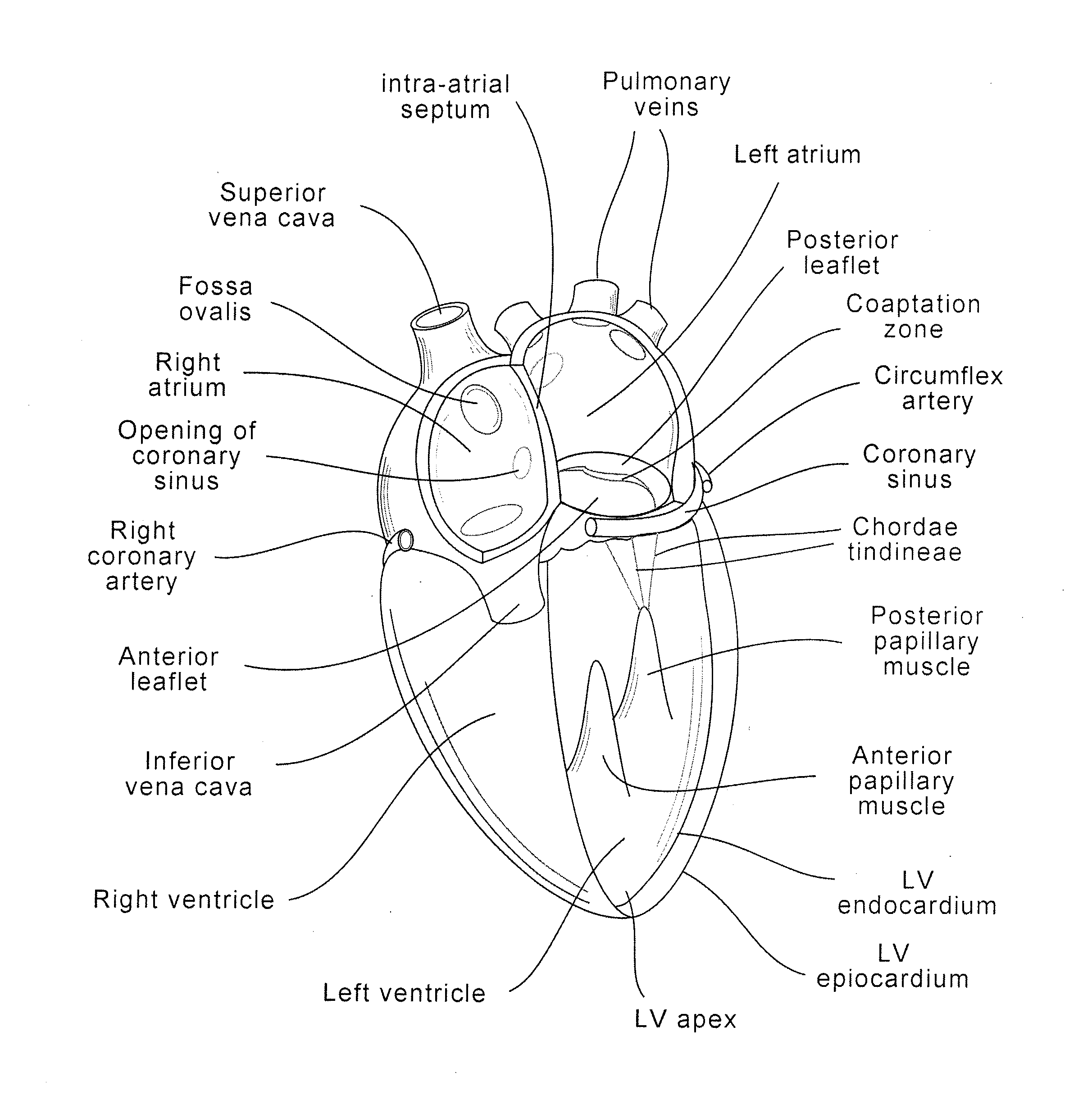
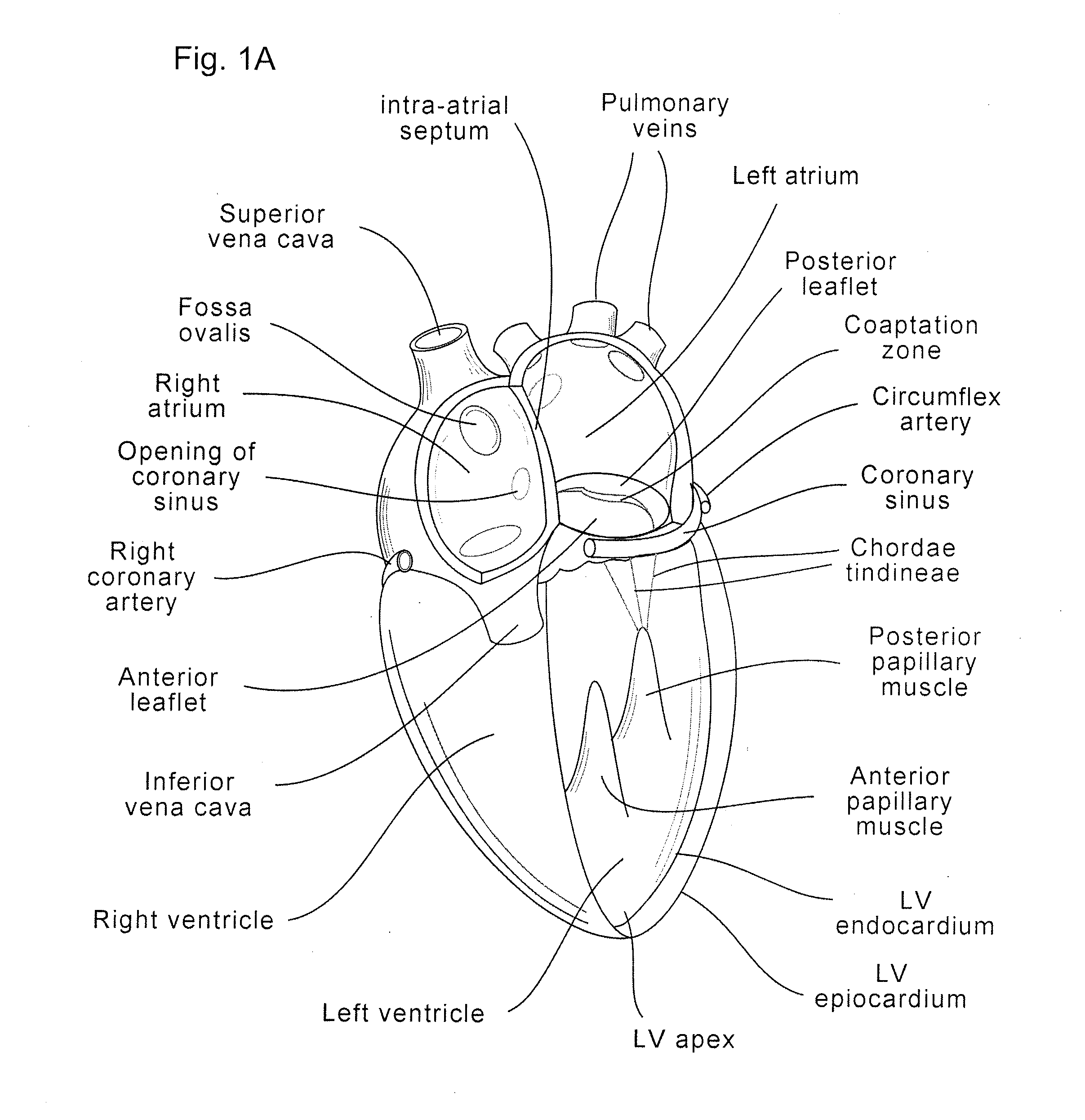
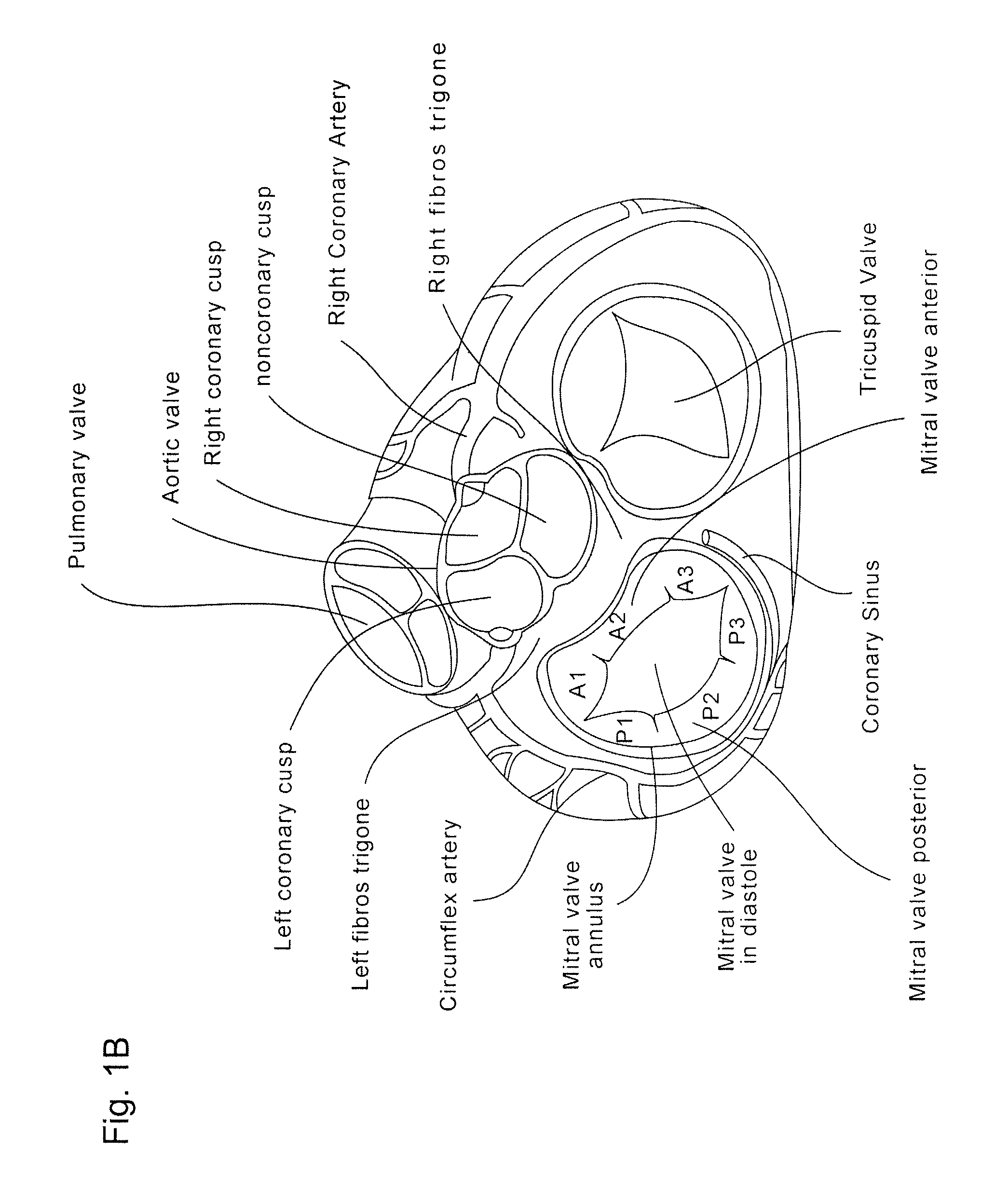
[0059]The present invention generally provides improved medical devices, systems, and methods, often for treatment of mitral valve regurgitation and other valve diseases. The implants described herein will generally include a coaptation assist body (sometimes referred to herein as a valve body) which is within the blood flow path as the leaflets of the valve move back and forth between an open-valve configuration (with the leaflets separated from valve body) and a closed-valve configuration (with the leaflets engaging opposed surfaces of the valve body). The valve body may structurally float or move within the annulus of the valve during beating of the heart, and will be disposed between the native leaflets to fill gaps between the coapting leaflet surfaces. Those gaps may be lateral (such as may be caused by a dilated left ventricle and / or mitral valve annulus) and / or axial (such as where one leaflet prolapses or is pushed by fluid pressure beyond the annulus when the valve should ...


PUM


Abstract

Implants, implant systems, and methods for treatment of mitral valve regurgitation and other valve diseases generally include a coaptation assist body which remains within the blood flow path as the leaflets of the valve move, the valve bodies often being relatively thin, elongate (along the blood flow path), and/or conformable structures which extend laterally from commissure to commissure, allowing the native leaflets to engage and seal against the large, opposed surfaces on either side of the valve body during the heart cycle phase when the ventricle contracts to empty that chamber of blood, and allows blood to pass around the valve body so that blood flows from the atrium to the ventricle during the filling phase of the heart cycle. Separate deployment of independent anchors near each of the commissures may facilitate positioning and support of an exemplary triangular valve body, with a third anchor being deployed in the ventricle. An outer surface of the valve body may accommodate tissue ingrowth or endothelialization, while a fluid-absorbing matrix can swell after introduction into the heart. The valve body shape may be selected after an anchor has been deployed, and catheter-based deployment systems may have a desirable low profile.

Description

[0001]This application claims priority from provisional U.S. patent application No. 61 / 437,397, titled “Coaptation Enhancement Implant, System, and Method” and filed Jan. 28, 2011, the entire disclosure of which is hereby incorporated by reference herein for all purposes.CROSS-REFERENCES TO RELATED APPLICATIONS[0002]NOT APPLICABLESTATEMENT AS TO RIGHTS TO INVENTIONS MADE UNDER FEDERALLY SPONSORED RESEARCH AND DEVELOPMENT[0003]NOT APPLICABLEREFERENCE TO A “SEQUENCE LISTING,” A TABLE, OR A COMPUTER PROGRAM LISTING APPENDIX SUBMITTED ON A COMPACT DISK[0004]NOT APPLICABLEBACKGROUND OF THE INVENTION[0005]The present invention generally provides improved medical devices, systems, and methods, typically for treatment of heart valve disease and / or for altering characteristics of one or more valves of the body. Exemplary embodiments of the invention include implants for treatment of mitral valve regurgitation.[0006]The human heart receives blood from the organs and tissues via the veins, pum...

Claims


Application Information

Patent Timeline
Patent Type & Authority Applications(United States)
IPC IPC(8): A61F2/24
CPCA61F2/246A61B2017/0649A61B17/0401A61B17/064A61B17/068A61F2/2454A61F2/2457A61B17/12122A61B17/12172A61B2017/00867A61B2017/0412A61B2017/0448A61B2017/0464A61B2017/048A61F2/2466A61F2250/0003
Inventor KHAIRKHAHAN, ALEXLESH, MICHAEL D.
Owner POLARES MEDICAL INC
Why Eureka
Try Eureka