Thin film piezoelectric element and manufacturing method thereof, micro-actuator, head gimbal assembly and disk drive unit with the same

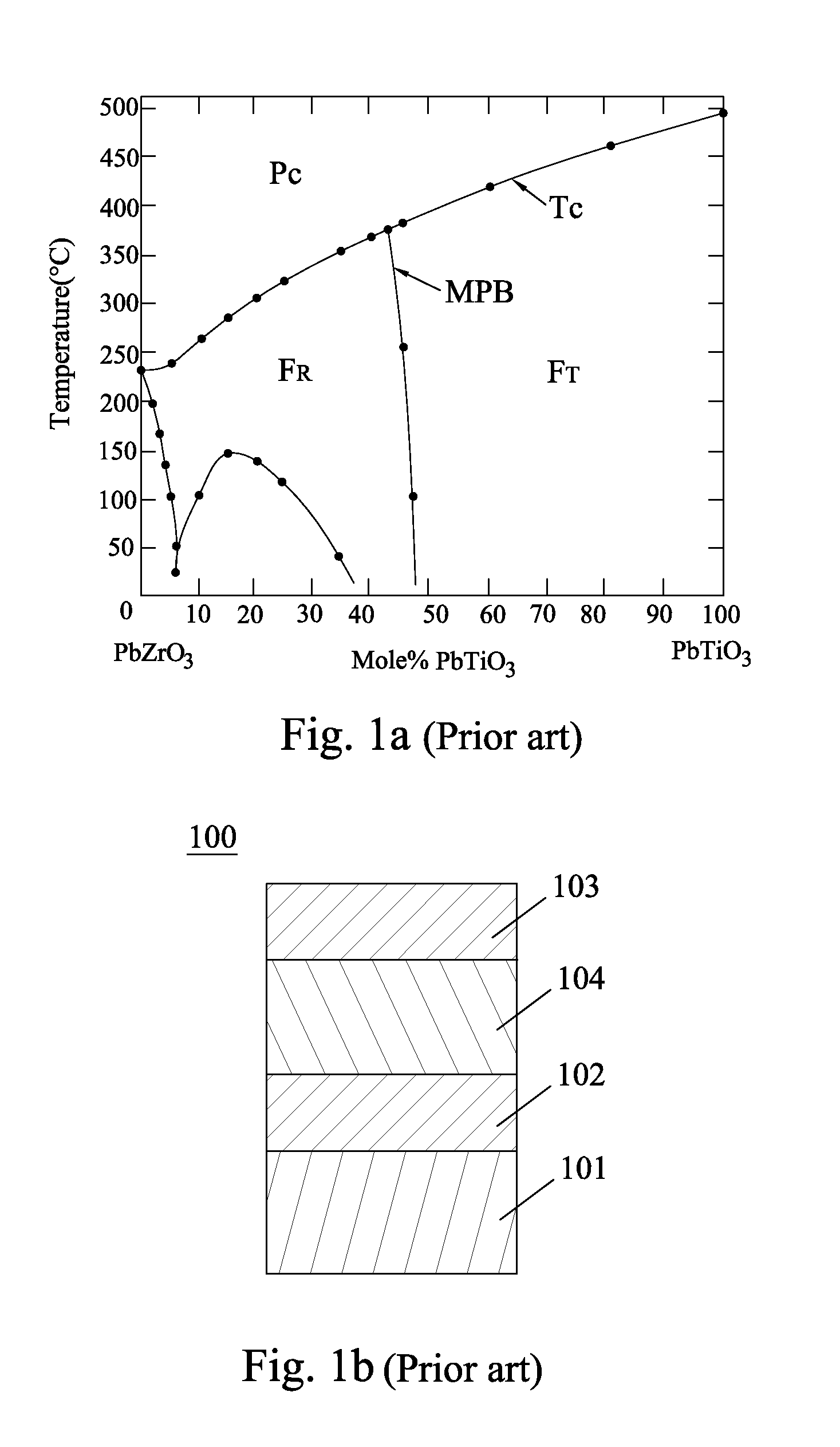
a piezoelectric element and film technology, applied in the field of piezoelectric elements, can solve the problems of limited field strength, unsatisfactory piezoelectric constant of single-phase piezoelectric element b>100/b>, and difficult to control the composition exactly located at the mpb, etc., to achieve enhanced coercive field strength, high piezoelectric constant, and good thermal stability

Active Publication Date: 2013-10-24
SAE MAGNETICS (HK) LTD
View PDF21 Cites 22 Cited by
  • Summary
  • Abstract
  • Description
  • Claims
  • Application Information

AI Technical Summary

Benefits of technology

[0008]One aspect of the present invention is to provide a thin film piezoelectric element thereby obtaining high piezoelectric constants, enhanced coercive field strength and good thermal stability, and in turns enabling larger applied field strength without depolarization and achieving a large stroke for its applied device.
[0009]Another aspect of the present invention is to provide a manufacturing method of a thin film piezoelectric element thereby obtaining high piezoelectric constants, enhanced coercive field strength and good thermal stability, and in turns enabling larger applied field strength without depolarization and achieving a large stroke for its applied device.
[0010]Yet an aspect of the present invention is to provide a micro-actuator with a thin film piezoelectric element, thereby obtaining high piezoelectric constants, enhanced coercive field strength and good thermal stability, and in turns enabling larger applied field strength without depolarization and achieving a large stroke for its applied device.

Problems solved by technology

However, it's quite hard to control the composition exactly located at the MPB.
However, the piezoelectric constants of this single-phase piezoelectric element 100 is still inadequate as the product requirement for stroke becomes higher and higher.
Moreover, the applied field strength is limited due to the single phase structure wherein the depolarization will occur at field strength larger than the coercive field strength (Ec).
However, it will bring high risk of delamination and reliability failure for the piezoelectric element.
Another way to enable larger applied field strength is to increase the PZT thickness, which will cause a rise in the cost however.
Based on the limitation on the piezoelectric constants and coercive field strength, the stroke of the piezoelectric element applied in the actuator or sensor is insufficient, which does not satisfy the requirement of the product manufacturer.

Method used


Image

  • Thin film piezoelectric element and manufacturing method thereof, micro-actuator, head gimbal assembly and disk drive unit with the same
  • Thin film piezoelectric element and manufacturing method thereof, micro-actuator, head gimbal assembly and disk drive unit with the same
  • Thin film piezoelectric element and manufacturing method thereof, micro-actuator, head gimbal assembly and disk drive unit with the same

Examples


Embodiment Construction

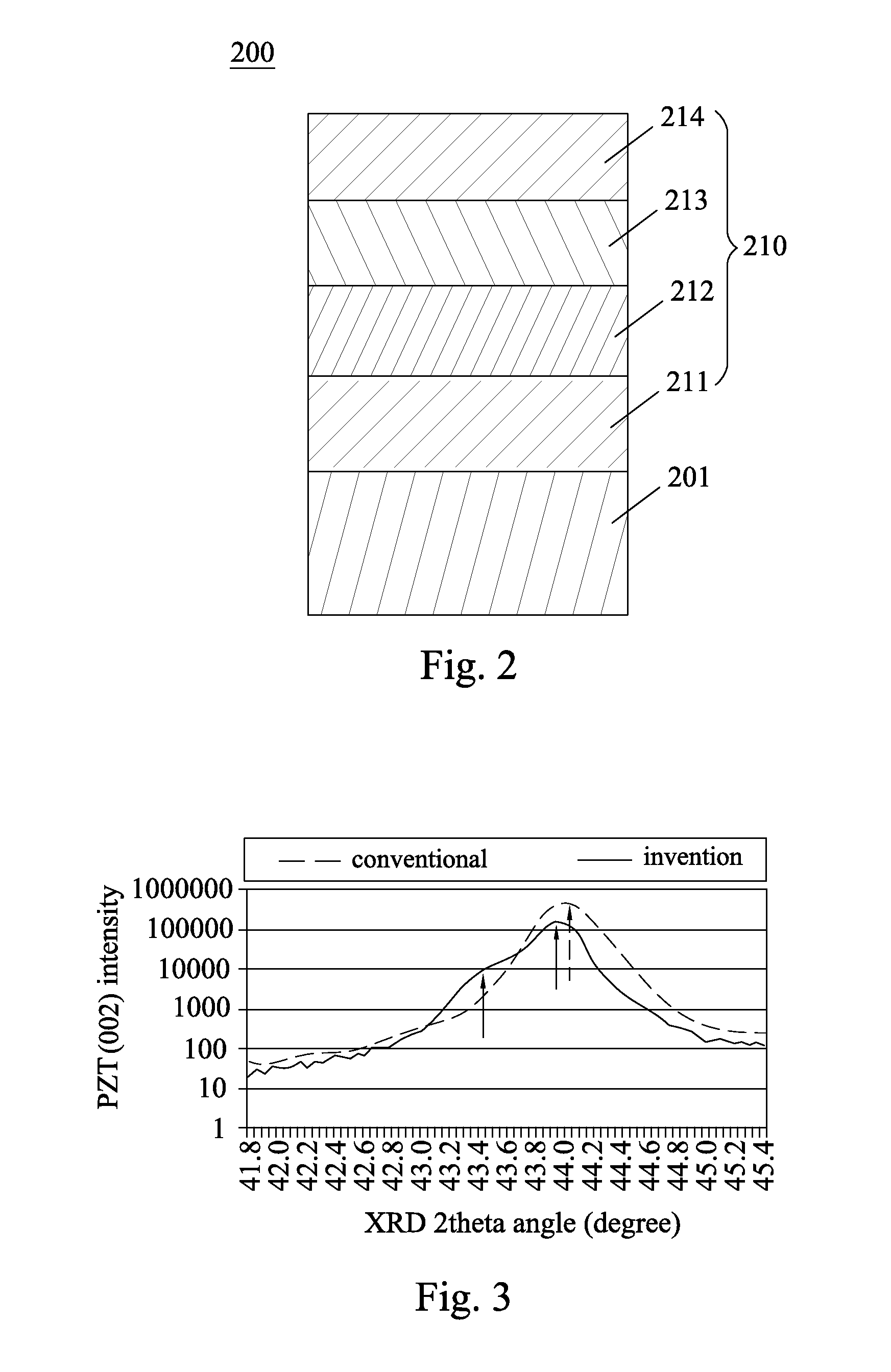
[0049]Various preferred embodiments of the invention will now be described with reference to the figures, wherein like reference numerals designate similar parts throughout the various views. As indicated above, the invention is directed to a thin film piezoelectric element thereby obtaining high piezoelectric constants, enhanced coercive field strength and good thermal stability, and in turns enabling larger applied field strength without depolarization and achieving a large stroke for its applied device.

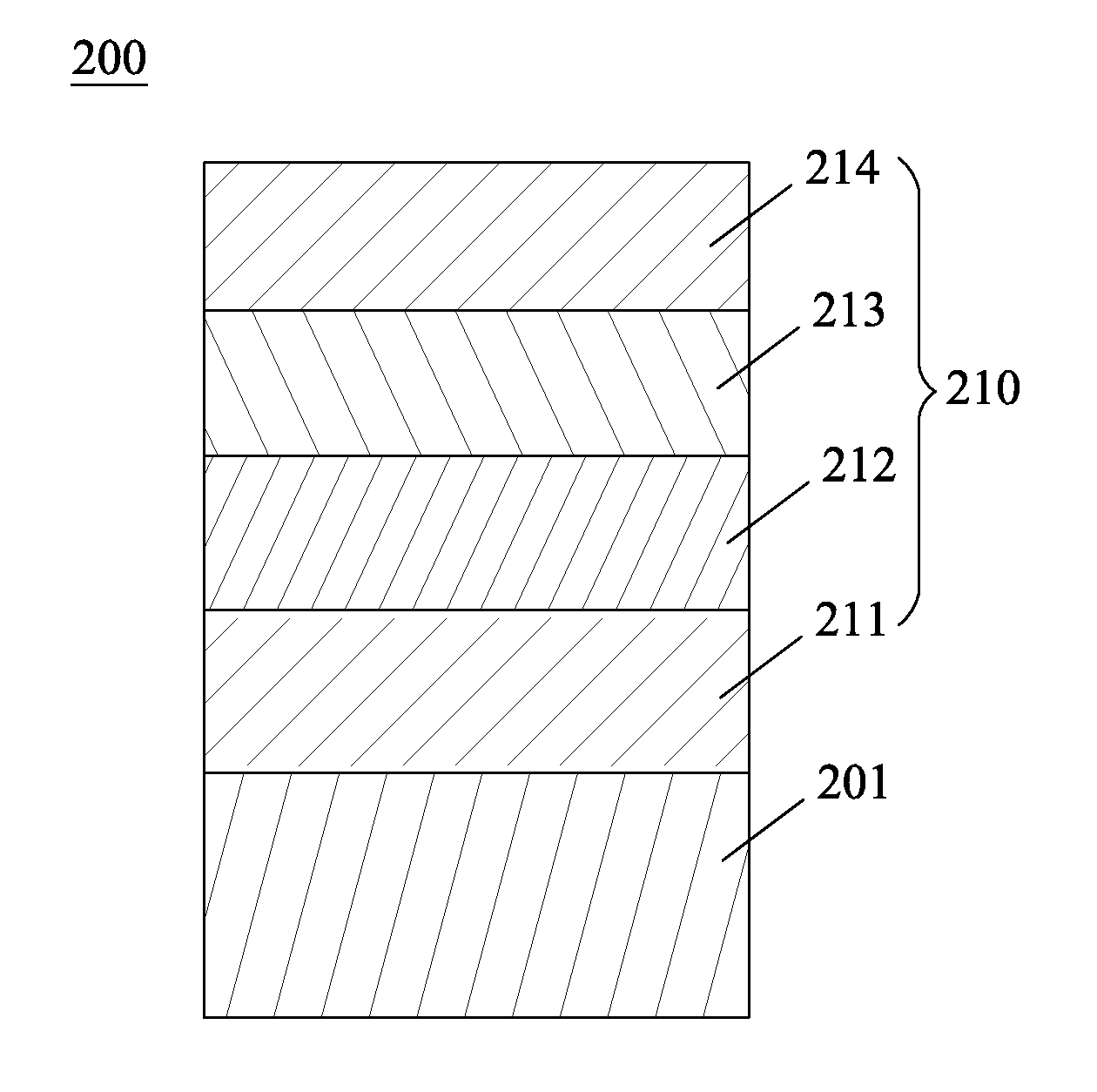
[0050]Referring to FIG. 2, a thin film piezoelectric element 200 according to one embodiment of the present invention includes a substrate 201 and a piezoelectric thin film stack 210 formed on the substrate 201. Concretely, the piezoelectric thin film stack 210 includes a bottom electrode layer 211 formed on the substrate 201, a first piezoelectric layer 212 and a second piezoelectric layer 213 formed on the bottom electrode layer 211 in turn, and a top electrode layer 214 covered ...


PUM

PropertyMeasurementUnit
thicknessaaaaaaaaaa
thicknessaaaaaaaaaa
thicknessaaaaaaaaaa

Abstract

A thin film piezoelectric element of the present invention includes a substrate and a piezoelectric thin film stack formed on the substrate. The piezoelectric thin film stack includes a top electrode layer, a bottom electrode layer and a piezoelectric layer sandwiched between the top electrode layer and the bottom electrode layer, wherein the piezoelectric layer includes a first piezoelectric layer and a second piezoelectric layer whose compositions have different phase structures. The present invention can obtain high piezoelectric constants, enhanced coercive field strength and good thermal stability, thereby enabling larger applied field strength without depolarization and achieving a large stroke for its applied device.

Description

FIELD OF THE INVENTION[0001]The present invention relates to a piezoelectric element, and more particularly, to a thin film piezoelectric element and manufacturing method thereof, a micro-actuator, a head gimbal assembly (HGA), and a disk drive unit with the same.BACKGROUND OF THE INVENTION[0002]Piezoelectric material is processed into various piezoelectric elements in accordance with different purposes, particularly, it has been widely used for functional electronic components such as an actuator for generating deformation by applying voltage or a sensor for generating voltage from the deformation of elements in a reverse way, etc.[0003]As the piezoelectric material used for an actuator in the disk drive unit for actuating the fine movements of the slider thereof, a lead (Pb)-based dielectric material having large piezoelectric characteristics, especially, Lead Zirconate Titanate Pb(Zr1-xTix)O3-based perovskite-type ferroelectric called as “PZT”, has been widely used, and the piezo...

Claims


Application Information

Patent Timeline
Patent Type & Authority Applications(United States)
IPC IPC(8): H01L41/18H01L41/297G11B21/16
CPCH01L41/18G11B21/16H01L41/297G11B5/483H10N30/1051H10N30/8554H10N30/076H10N30/85H10N30/067
Inventor XIONG, WEIROKRAKTHONG, PANJALAKHATA, KENJIRONISHIYAMA, KAZUSHIIITSUKA, DAISUKEIIJIMA, ATSUSHI
Owner SAE MAGNETICS (HK) LTD
Why Eureka
Try Eureka