Thermoelectric cooling systems

a technology of thermal insulation and cooling system, applied in the direction of refrigerating machines, machines using electric/magnetic effects, tubular elements, etc., can solve the problems of lowering the thermal resistance inside the heat pipe, and achieve the effect of high coefficient of performance and ease of operation

Inactive Publication Date: 2013-11-07
SHEETAK INC
View PDF9 Cites 27 Cited by
  • Summary
  • Abstract
  • Description
  • Claims
  • Application Information

AI Technical Summary

Benefits of technology

[0007]The present disclosure provides thermoelectric cooling systems with optimized positionin

Problems solved by technology

Further, when the cross sectional area of the heat pipes increases it results in a l

Method used


Image

  • Thermoelectric cooling systems
  • Thermoelectric cooling systems
  • Thermoelectric cooling systems

Examples


Embodiment Construction

[0034]Before describing the embodiments in detail, in accordance with the present invention, it should be observed that these embodiments reside primarily in the method and apparatus for cooling of fluids. Accordingly, the steps involved in the method and the system components have been represented to show only those specific details that are pertinent for understanding the embodiments of the present invention, and not the details that will be apparent to those with ordinary skill in the art.

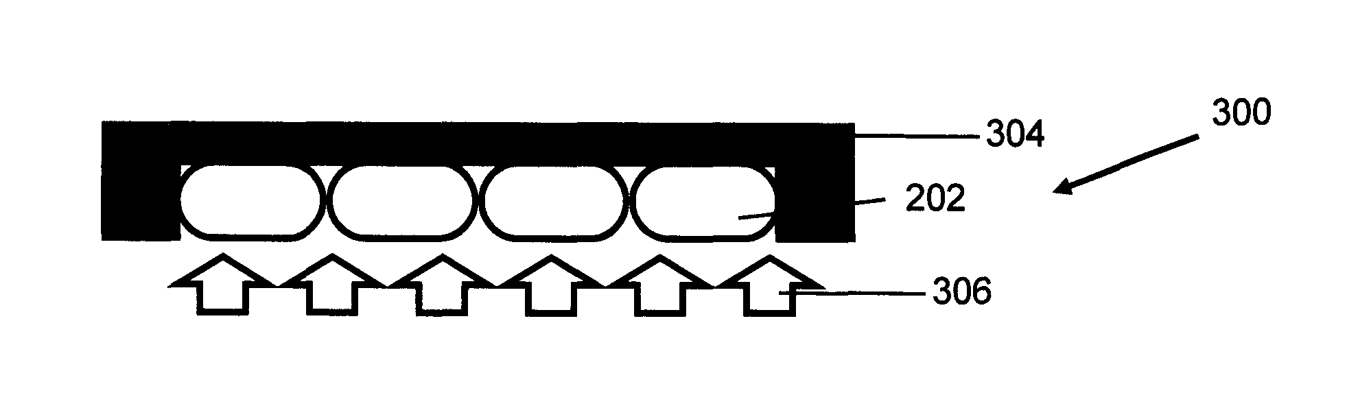
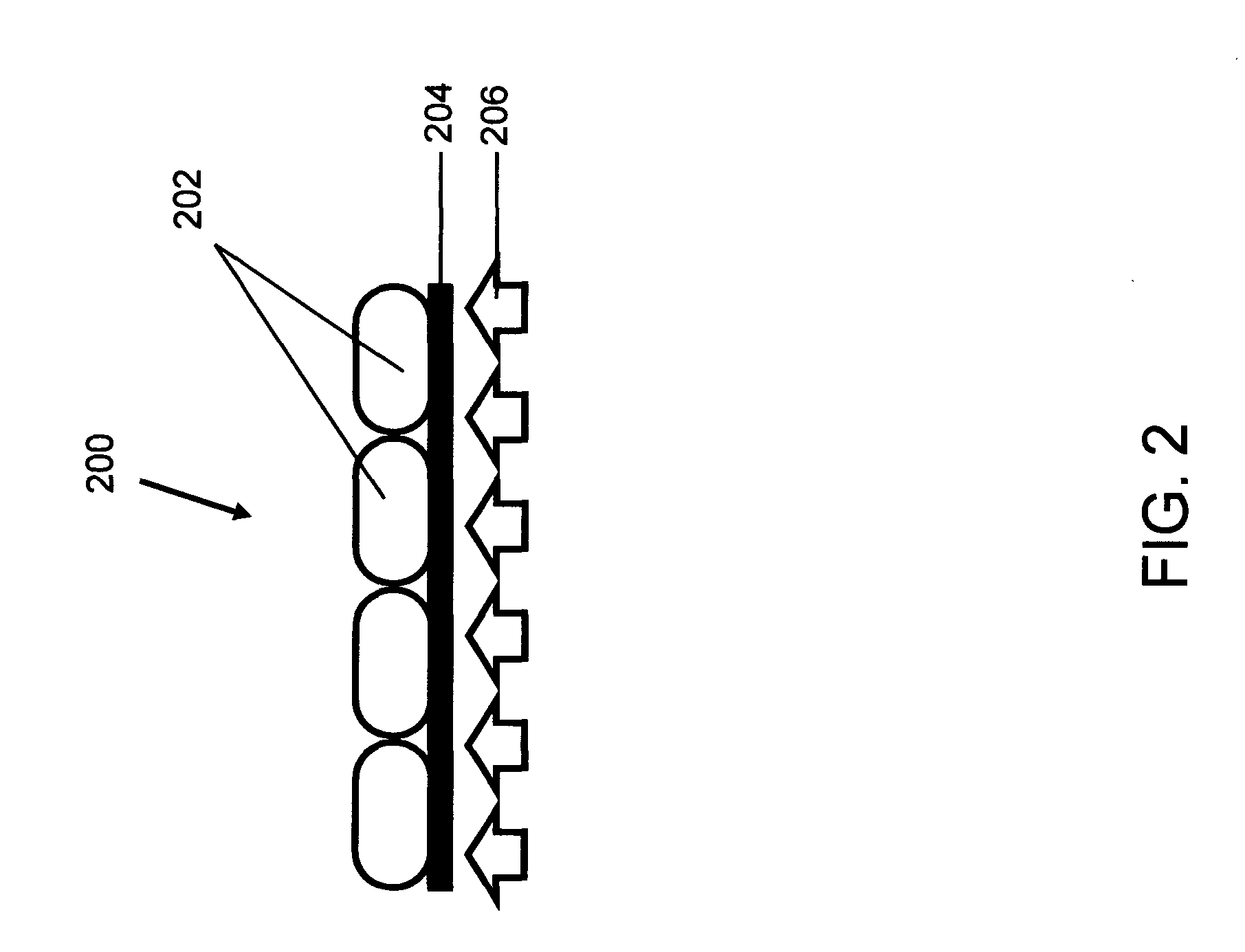
[0035]FIG. 1 illustrates a conventional assembly of heat pipes. FIGS. 2 to 4 illustrate heat pipes, in accordance with various embodiments of the present disclosure.

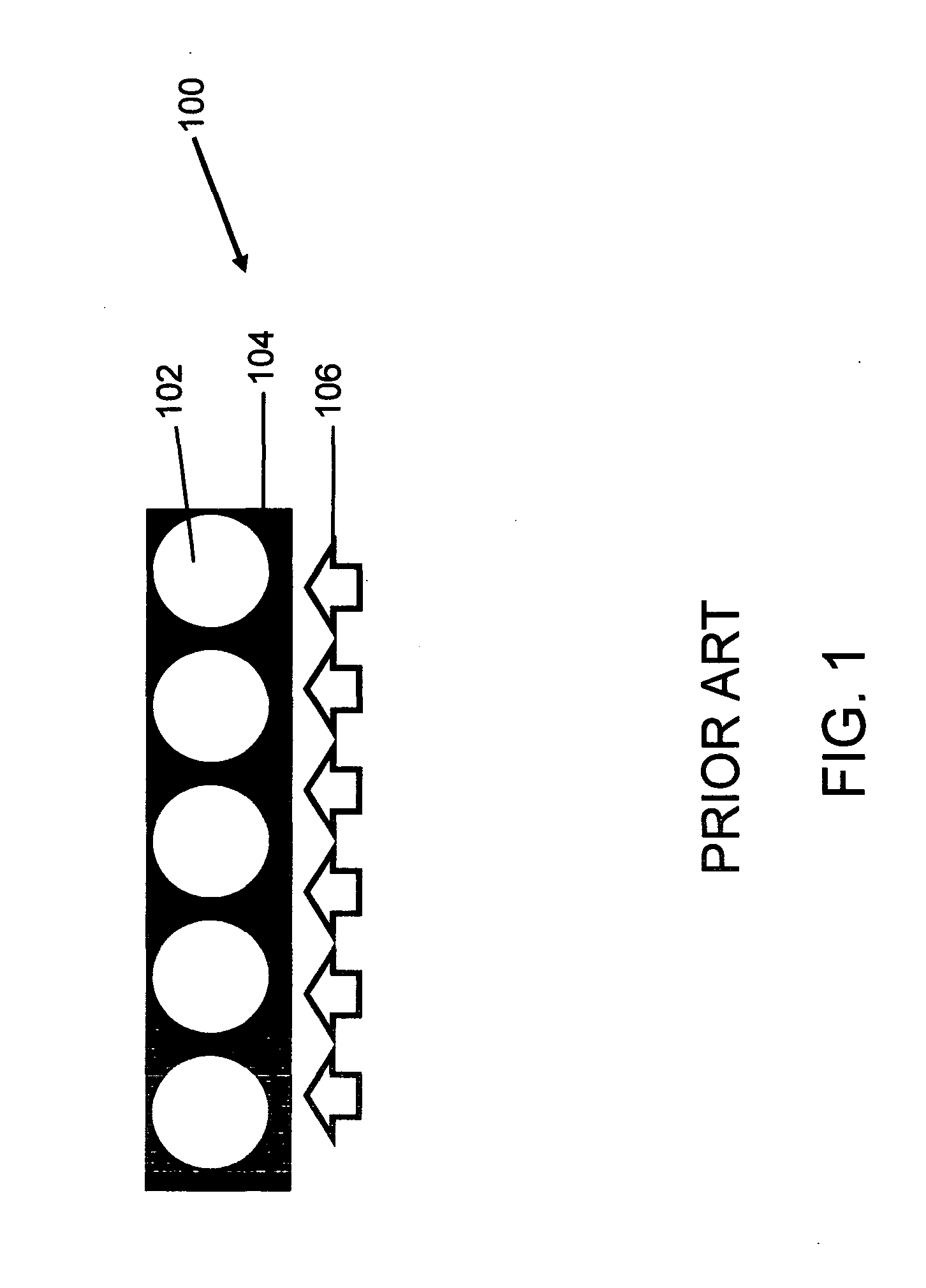
[0036]FIG. 1 is a schematic cross-sectional diagram of a conventional assembly of heat pipes 100.

[0037]The assembly of heat pipes 100 comprises heat pipes 102 having a circular cross sectional area embedded in a metal block 104. Metal block 104 comprises circular cavities in which heat pipes 102 are embedded. Preferably, heat pipes 1...


PUM


Abstract

The present disclosure provides a thermoelectric cooling system with improved performance. The thermoelectric cooling system comprises a thermoelectric cooling unit. The thermoelectric cooling unit comprises a thermoelectric device, heat pipes, condenser fins, a cold sink and a cold fan. The thermoelectric cooling unit can be easily assembled with a chamber which contains a fluid to be cooled. The thermoelectric cooling system comprises screws to attach the thermoelectric cooling unit to the chamber, and sealant rings to prevent heat leakage in the thermoelectric cooling system. Further, the present disclosure provides a thermoelectric cooling system with a freezer part and a refrigerator part. The freezer part encloses the cold sink and the cold fan. The freezer part is cooled by the thermoelectric device, and the refrigerator part is cooled by walls of the freezer part. Further, the present disclosure provides a thermoelectric cooling system for use as a wine cooler.

Description

BACKGROUND[0001]1. Technical Field of the Invention Disclosure[0002]The present disclosure relates to the field of thermoelectric cooling systems for cooling a fluid. More specifically, the present disclosure relates to compact thermoelectric cooling systems such as thermoelectric refrigerators with optimized positioning of elements.[0003]2. Description of Related Art[0004]The most widely used cooling system is a vapor compression cooling system. The vapor compression system uses chlorofluorocarbon (CFC) refrigerants such as Freon, hydrochloroflourocarbon. (HCFC) refrigerants such as R134, or hydroflourocarbons (HFC) refrigerants such as R410 for cooling. The use of CFC refrigerants in the vapor compression system causes emission of green house gases (GHG), which is an environmental threat. Further, such refrigerants may result in depletion of the ozone layer. Depletion of the ozone layer is an environmental hazard because the ozone layer filters ultraviolet radiation from sunlight....

Claims


Application Information

Patent Timeline
IPC IPC(8): F25B21/02
CPCF25B21/02F25B2321/023F28D15/0275F28F1/325F28D2021/0028H05K7/20336H10N10/13
Inventor GHOSHAL, UTTAMGUHA, AYANPOCKHAMA, HIMANSHU
Owner SHEETAK INC
Why Eureka
Try Eureka