Gasification melting furnace and method for treating combustible material using the same

a gasification melting furnace and combustible material technology, applied in the direction of combustible gas production, plasma technique, molten salt/metal gasification, etc., can solve the problems of not being able to stably reach a high temperature not less than 1,000°, and not being able to achieve slag. , to achieve the effect of efficient treatment of a large amount of was

Inactive Publication Date: 2013-11-07
GS PLATECH
View PDF6 Cites 3 Cited by
  • Summary
  • Abstract
  • Description
  • Claims
  • Application Information

AI Technical Summary

Benefits of technology

[0012]Accordingly, an aspect of the present invention is to provide a gasification melting furnace effic

Problems solved by technology

However, during incineration, a large amount of air contaminants (SOx, NOx, dioxin, etc.) and heavy metals in an amount of 10 to 20% of input are eluted, and incinerated ash requiring landfill is generated.
However, most of currently developed gasification methods have significant difficulties in stably applying enthalpies required for gasification due to oxidation of a part of an input material, on the basis of uniformity of the input material and characteristics of waste having low calories.
Additionally, since a thermal equilibrium temperature in the gasification is relatively low, it is considerably difficult to stably reach a high temperature of not less than 1,000° C. Also, an exhaust gas containing an unburned fraction or un-decomposed contaminants in large amounts will be probably discharged.
Further, due to low temperature, what is obtainable may not be slag but ash.
However, it is not easy to control a transfer speed of the was

Method used


Image

  • Gasification melting furnace and method for treating combustible material using the same
  • Gasification melting furnace and method for treating combustible material using the same
  • Gasification melting furnace and method for treating combustible material using the same

Examples


first embodiment

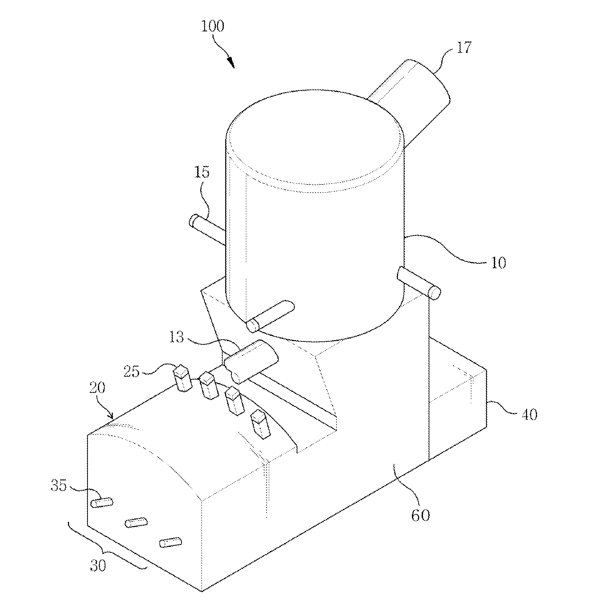
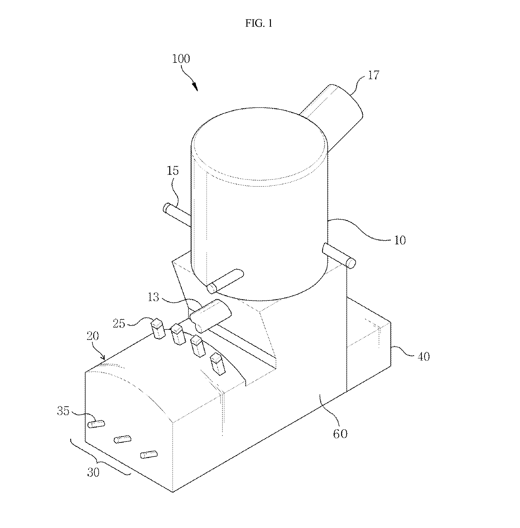
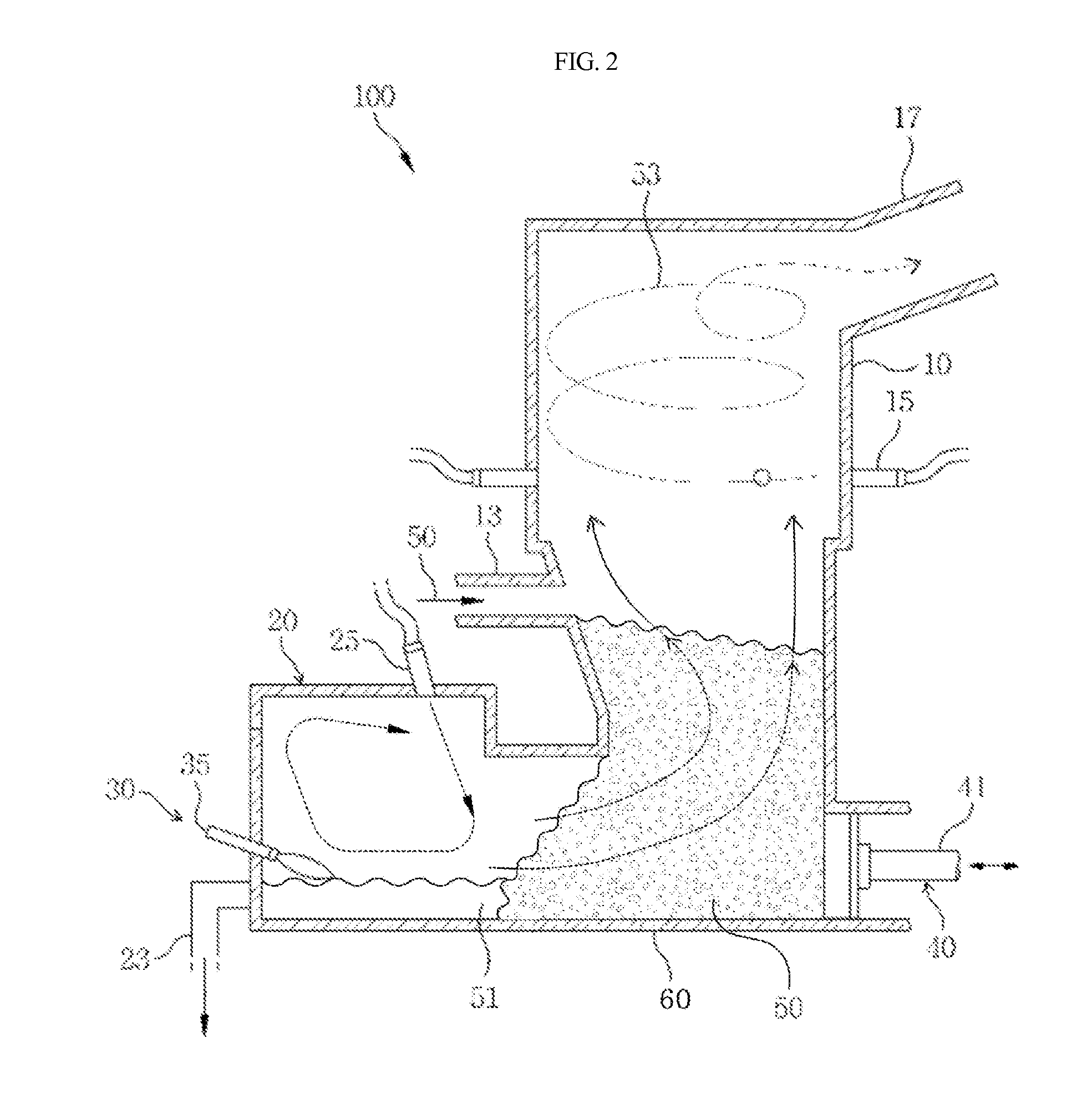
[0060]FIG. 1 is a perspective view illustrating a gasification melting furnace according to the first embodiment of the present invention, FIG. 2 is a cross-sectional view illustrating the gasification melting furnace shown in FIG. 1, and FIG. 3 is a cross-sectional view illustrating a gasification part of the furnace shown in FIG. 1.

[0061]Referring to FIGS. 1 to 3, the gasification melting furnace 100 according to the first embodiment of the present invention includes a gasification part 10, a melting part 20 and a sedimentary part 60. A combustible material 50 being input from the gasification part 10 is deposited in the sedimentary part 60, combustible components in the combustible material are converted into a synthetic gas 53 by a heater in the melting part 20, and the generated synthetic gas 53 is transferred through a sedimentary body formed of combustible materials 50 to the gasification part 10.

[0062]In this regard, gasification and partial oxidation carried out in the gasi...

second embodiment

[0086]Although the first embodiment described an example of the gasification part 10 configured in a cylindrical shape, the configuration of the gasification part is not particularly limited to the above example. As shown in FIGS. 4 and 5, a gasification part 110 may be configured in a rectangular tube shape. Herein, FIG. 4 is a perspective view illustrating a gasification melting furnace 200 according to a second embodiment of the present invention. Also, FIG. 5 is a cross-sectional view illustrating the gasification part 110 shown in FIG. 4.

[0087]Referring to FIGS. 4 and 5, the gasification melting furnace 200 according to the second embodiment has substantially the same construction as the gasification melting furnace 100 according to the first embodiment, except that the gasification part 110 is configured in a rectangular tube shape. Therefore, the following description will be focused on the gasification part 110.

[0088]The gasification part 110 is connected to the top side of ...

third embodiment

[0089]Although the first embodiment described an example in that an outlet 317 for discharging an exhaust gas including the synthetic gas 53 through the gasification part 10 is provided on a lateral face of the top side of the gasification part 10, in consideration of actually limited conditions such as an exit or height problem, a configuration of the outlet is not particularly limited to the above example. For instance, as shown in FIGS. 6 and 7, in order to inhibit escape of an unburned fraction or ash, the outlet 317 of the gasification part 10 may be provided to locate at the center of an upmost part of the gasification part 10. Herein, FIG. 6 is a perspective view illustrating a plasma gasification melting furnace 300 according to a third embodiment of the present invention. Also, FIG. 7 is a cross-sectional view illustrating the gasification melting furnace 300 shown in FIG. 6. The same parts as in the first embodiment will be denoted by the same reference numerals, descripti...


PUM


Abstract

A gasification melting furnace includes a gasification part into which the combustible material inputs, a sedimentary part communicating with a lower part of the gasification part, and a melting part communicating with a lateral face of the sedimentary part and having a heater, wherein the sedimentary part is filled with the combustible material and a gas generated in the melting part passes through the combustible material and inputs into the gasification part, thereby stably and rapidly treating the combustible material, reducing energy consumption of the heater, and providing a synthetic gas containing decreased hazardous substances.

Description

CROSS REFERENCE TO RELATED APPLICATIONS AND CLAIM OF PRIORITY[0001]This application claims priority to Korean Patent Application No. 10-2012-0047755, filed on May 4, 2012 and Korean Patent Application No. 10-2012-0047757, filed on May 4, 2012, in the Korean Intellectual Property Office, the entire disclosure of which is incorporated herein by reference.BACKGROUND[0002]1. Field of the Invention[0003]The present invention relates to a melting furnace for gasification and, more particularly, to a gasification melting furnace used for treating a waste-containing combustible material to generate energy therefrom.[0004]2. Description of the Related Art[0005]A reaction of converting combustible waste into energy may be assorted into incineration (burning) performed under an oxygen-rich atmosphere and gasification conducted under an oxygen-depleted atmosphere. Most of the waste generates hot exhaust gas through incineration and steam is recovered from waste heat of the exhaust gas. However,...

Claims


Application Information

Patent Timeline
IPC IPC(8): H05H1/26
CPCH05H1/26C10J2200/12C10J3/08C10J3/18C10J3/57C10J2300/1238C10J2200/154
Inventor KIM, YOUNG-SUKHWANG, SOON-MODO, CHUL-JINLEE
Owner GS PLATECH
Why Eureka
Try Eureka