Acoustic transducer

a transducer and acoustic technology, applied in the field of acoustic transducers, can solve the problems of weak ecm against heat, deterioration of sound quality, and difficulty for low-sensitivity microphones to detect small sound with high quality, and achieve the effect of reducing the variation between chips

Active Publication Date: 2013-11-07
ORMON CORP +1
View PDF25 Cites 32 Cited by
  • Summary
  • Abstract
  • Description
  • Claims
  • Application Information

AI Technical Summary

Benefits of technology

[0016]Moreover, the plurality of variable capacitors are formed between the same vibrating membrane and the same fixed membrane. Hence, according to the present disclosure, the chips have similar variations between the detection sensitivities of the respective variable capacitors, in comparison with the conventional technique by which the plurality of vibrating membranes and the plurality of fixed membranes ...

Problems solved by technology

However, the ECM is weak against heat.
This is because attempting to detect a large sound by the microphone results in generation of a harmonic distortion in an output signal, thereby leading to deterioration of sound quality.
This is because the high-sensitivity microphone tends to output a large signal and therefore is likely to cause the THD.
However, it is difficult for the low-sensitivity microphone to detect a small sound with high quality.
However, according to the abov...

Method used


Image

  • Acoustic transducer
  • Acoustic transducer
  • Acoustic transducer

Examples


first embodiment

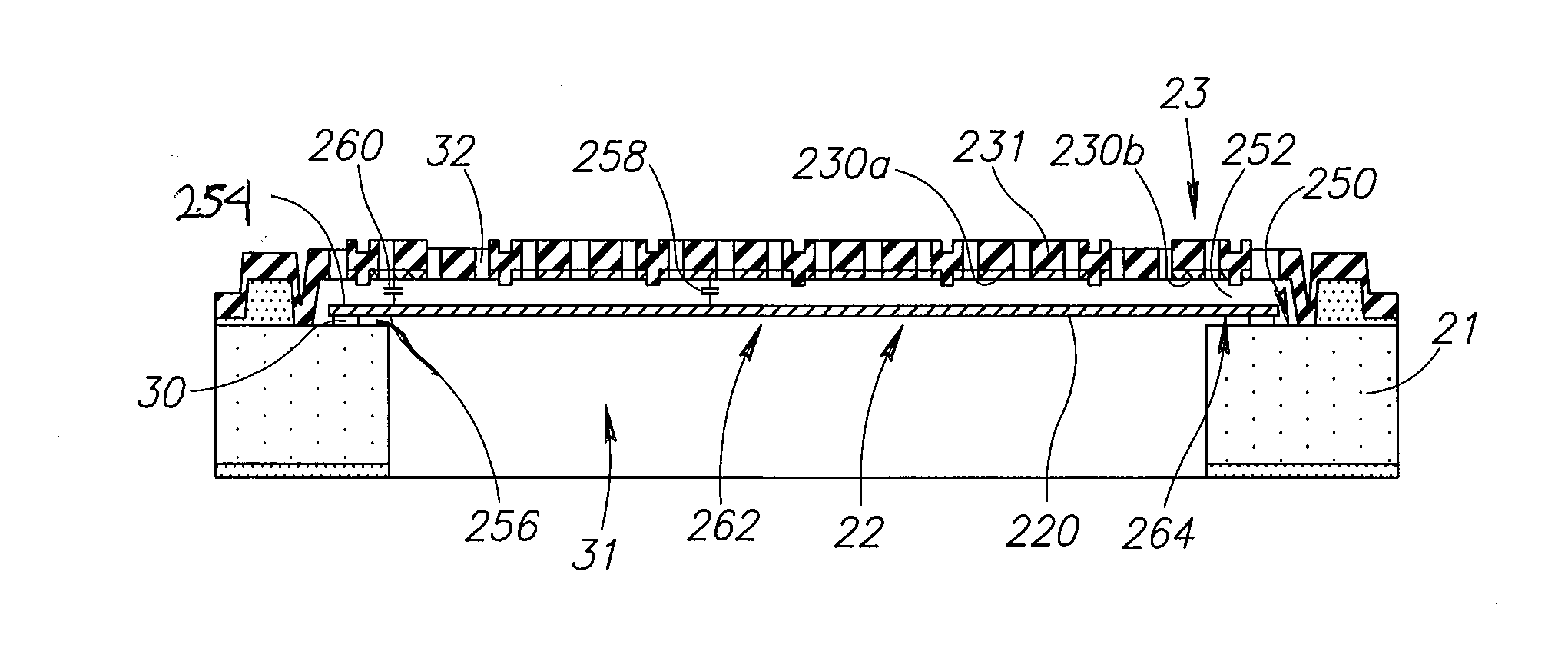
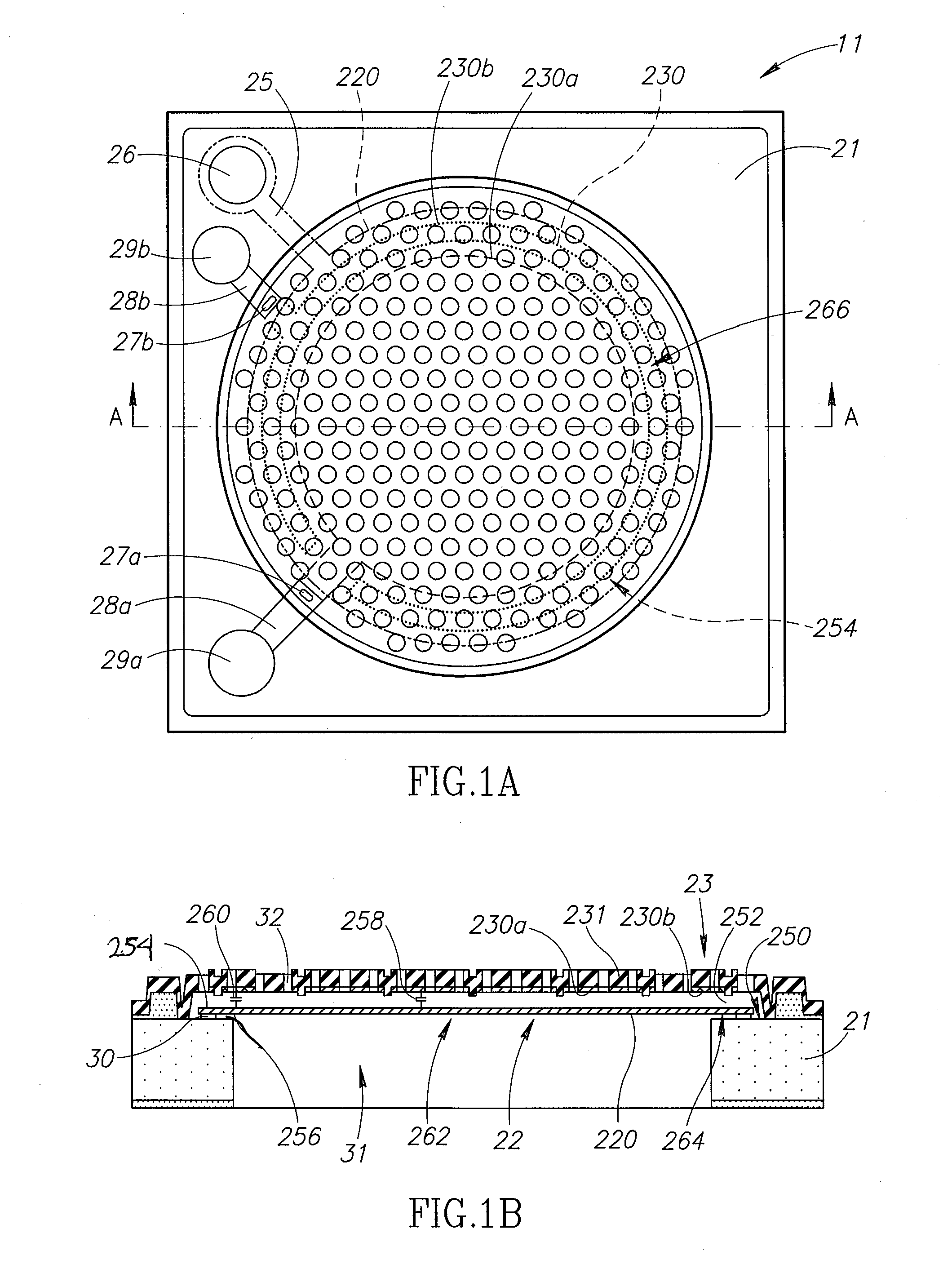
[0037]The following describes an embodiment of the present disclosure with reference to FIGS. 1A to 3. FIGS. 1A and 1B are top down and cross-sectional views of the acoustic sensor 11 in this embodiment. FIG. 1A is a top plan view of the acoustic sensor 11, and FIG. 1B is an enlarged cross-sectional view of the acoustic sensor 11, taken along line A-A shown in FIG. 1A and viewed in an arrow direction shown in FIG. 1A.

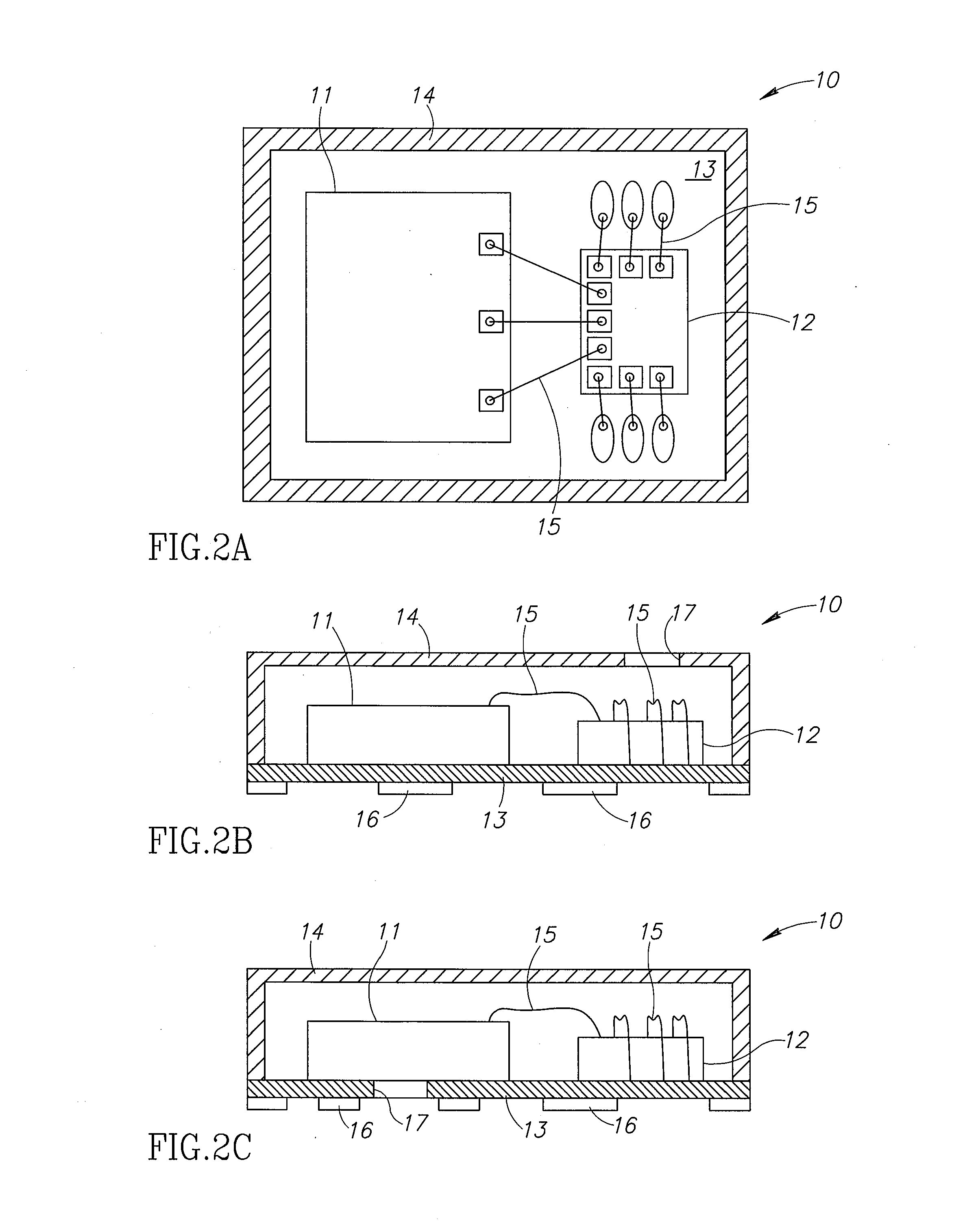
[0038]FIGS. 2A to 2C show a schematic configuration of a MEMS microphone package of this embodiment. FIG. 2A is a plan view showing a portion of the MEMS microphone package with an upper portion of the package cut away. FIGS. 2B and 2C are front views showing the MEMS microphone packages with a front portions cut away. Note that FIG. 2C is a modification of the configuration shown in FIG. 2B.

[0039]As shown in FIG. 2A, the MEMS microphone package 10 includes an acoustic sensor (acoustic transducer) 11, an ASIC 12, a wiring board or printed circuit board 13, and a cover 1...

second embodiment

[0072]Next, a description is made of another embodiment of the present disclosure with reference to FIGS. 4A and 4B. FIGS. 4A and 4B show a schematic configuration of an alternative embodiment of the acoustic sensor 11; where FIG. 4A is a top plan view of the acoustic sensor 11, and FIG. 4B is an enlarged cross-sectional view of the acoustic sensor 11, taken along line B-B of FIG. 4A.

[0073]The acoustic sensor 11 shown in FIGS. 4A and 4B is different from the acoustic sensor 11 shown in FIGS. 1A and 1B in that the insulating layer 30 is not present, the edge 254 of a vibrating membrane 22 is not fixed to a semiconductor substrate 21, and protruding portions 232 extend from a protecting membrane 231 of a fixed membrane 23 to the vibrating membrane 22. The protruding portions 232 are coupled to the vibrating membrane 22 and support the vibrating membrane from above, in this configuration. In some package arrangements, the acoustic sensor 11 will be in a different arrangement. For examp...

third embodiment

[0078]Next, a description is made of still another embodiment of the present disclosure with reference to FIGS. 5 and 6. FIG. 5 is a plan view showing an acoustic sensor 270 according to this embodiment. The plan view of FIG. 5 is a view of a vibrating membrane 272 not covered by a protecting membrane. Locations 274 where the protecting membrane couples to a substrate 276 of the sensor 270 are shown.

[0079]The membrane 272 includes a first portion 278 centrally positioned with respect to a second portion 280. The protecting membrane is not shown; however, an outline of a first electrode 284 and a second electrode 286 coupled to the protecting membrane are shown with solid lines. The protecting membrane is a fixed membrane that is configured to hold the first and second electrodes 284 and 286 in place as the vibrating membrane 272 moves in response to sound waves. The second electrode 286 surrounds the first electrode 284 on all sides, except for an opening 288 where a first extension...


PUM


Abstract

Provided is an acoustic transducer including: a semiconductor substrate; a vibrating membrane provided above the semiconductor substrate, including a vibrating electrode; and a fixed membrane provided above the semiconductor substrate, including a fixed electrode, the acoustic transducer detecting a sound wave according to changes in capacitances between the vibrating electrode and the fixed electrode, converting the sound wave into electrical signals, and outputting the electrical signals. At least one of the vibrating electrode and the fixed electrode is divided into a plurality of divided electrodes, and the plurality of divided electrodes outputting the electrical signals.

Description

BACKGROUND[0001]1. Technical Field[0002]The present disclosure relates to an acoustic transducer that converts a sound wave into electrical signals, and to a microphone including the acoustic transducer.[0003]In particular, the present disclosure relates to an acoustic transducer having a split membrane.[0004]2. Description of the Related Art[0005]Conventionally, an ECM (Electret Condenser Microphone) has been widely used as a miniature microphone mounted on a cellular (mobile) phone and the like. However, the ECM is weak against heat. On the other hand, a MEMS microphone is superior to the ECM in terms of digitalization, miniaturization, enhancement of functionality / multi-functionality, and power savings. Accordingly, at present, the MEMS microphone is becoming widespread.[0006]The MEMS microphone includes a capacitor-type acoustic sensor (acoustic transducer) that detects a sound wave and converts the detected sound wave into an electrical signal (detection signal), a drive circui...

Claims


Application Information

Patent Timeline
IPC IPC(8): H04R3/00
CPCH04R3/00H04R1/086H04R3/005H04R19/005H04R19/016H04R19/04H04R31/00H04R2499/11B81B3/0021H04R1/023H04R2201/003
Inventor KASAI, TAKASHISATO, SHOBUUCHIDA, YUKIPADOVANI, IGINODAVID, FILIPPOCONTI, SEBASTIANO
Owner ORMON CORP
Why Eureka
Try Eureka