Method of recovering ammonia and method of recycling ammonia by using the same

a technology of ammonia and ammonia, which is applied in the field of recovering ammonia and recycling ammonia by using the same, can solve the problem of small amount of adsorption and recovery ammonia, and achieve the effect of easy purification and easy recovery of ammonia

Active Publication Date: 2013-11-28
JAPAN PIONICS
View PDF1 Cites 4 Cited by
  • Summary
  • Abstract
  • Description
  • Claims
  • Application Information

AI Technical Summary

Benefits of technology

[0012]The method of recovering ammonia according to the present invention can efficiently easily recover ammonia from exhaust gas containing ammonia, hydrogen, nitrogen, and a solid compound, the exhaust gas being exhausted from a production process of a gallium nitride compound semiconductor. Furthermore,...

Problems solved by technology

The ammonia gas-recovery unit described in JP 2000-317246 A has the...

Method used


Image

  • Method of recovering ammonia and method of recycling ammonia by using the same
  • Method of recovering ammonia and method of recycling ammonia by using the same
  • Method of recovering ammonia and method of recycling ammonia by using the same

Examples


example 1

Production of Vapor Deposition Device

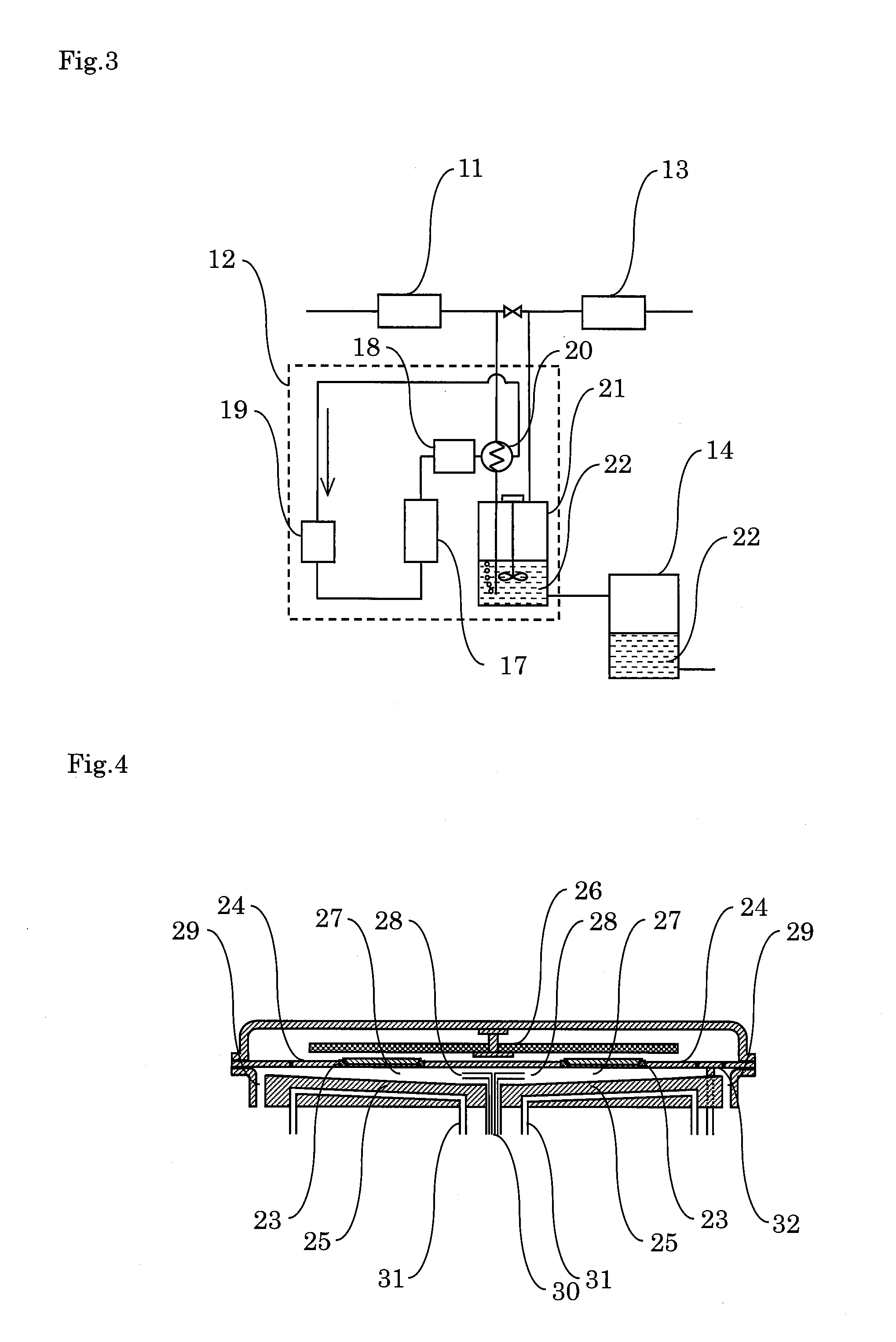
[0038]In a stainless steel reaction container, a disc susceptor 24 (material: SiC-coated carbon, diameter: 600 mm, thickness: 20 mm, capable of holding five 3-inch substrates), a part to which the susceptor faces 25 (material: carbon), in which refrigerant flows, a heater 26, a source gas-introducing unit 28 (material: carbon), a reactant gas-exhausting unit 29, and the like were provided to produce a vapor deposition device 9 with a reactor 27 as shown in FIG. 4. Then, five substrates, each consisting of a 3-inch sapphire, were set in substrate holders 23. As a flow path 31 flowing refrigerant, one pipe was disposed in form of helix from the center to the circumference.

[0039]In the source gas-introducing unit, three gas jetting ports were formed. The gas jetting ports each were vertically separated by two disc partitions with a diameter of 200 mm and a thickness of 2 mm (material: carbon). Of the three gas jetting ports, the upper jetting port s...

example 2

Ammonia-Recycling Experimentation

[0045]Liquid ammonia recovered as described above was sent to the liquid ammonia storage tank 14. After the vapor deposition was prepared as described above, the recovered liquid ammonia was evaporated by the vaporizer 5 and supplied to the gas mixer 15. At the same time, from the ammonia supply source, industrial ammonia was added and mixed with the recovered ammonia in an amount equal to the amount of ammonia removed after the recovering. The mixed ammonia was supplied for the vapor deposition through the purifier. The supplied amount ratio of the recovered liquid ammonia and the industrial ammonia was 79:21.

[0046]In the same way as Example 1, after the buffer layer was grown, the substrates were heated to 1050° C., ammonia (flow rate: 30 L / min), TMG (flow rate: 60 cc / min) and hydrogen (flow rate: 30 L / min), nitrogen (flow rate: 40 L / min) were supplied from the upper jetting port, the middle jetting port, and the lower jetting port, respectively, a...

example 3

Ammonia-Re-Recycling Experimentation

[0047]Liquid ammonia recovered as described above was sent to the liquid ammonia storage tank 14 in the same way as Examples 1 and 2. After the vapor deposition was prepared in the same way as Example 2, the recovered liquid ammonia was evaporated by the vaporizer 5 and supplied to the gas mixer 15. At the same time, from the ammonia supply source, industrial ammonia was added and mixed with the recovered ammonia. The mixed ammonia was supplied for the vapor deposition through the purifier. The supplied amount ratio of the recovered liquid ammonia and the industrial ammonia was 90:10.

[0048]In the same way as Examples 1 and 2, after the buffer layer was grown, the substrates were heated to 1050° C., ammonia (flow rate: 30 L / min), TMG (flow rate: 60 cc / min) and hydrogen (flow rate: 30 L / min), nitrogen (flow rate: 40 L / min) were supplied from the upper jetting port, the middle jetting port, and the lower jetting port, respectively, and a gallium nitr...


PUM


Abstract

There are provided methods capable of easily and efficiently recovering and recycling ammonia from exhaust gas containing a small amount of ammonia, the exhaust gas being exhausted from a production process of a gallium nitride compound semiconductor. The method of recovering ammonia includes filtering exhaust gas containing ammonia, hydrogen, nitrogen, and a solid compound with a filter to remove the solid compound from the exhaust gas; pressurizing and cooling the filtered exhaust gas with a heat pump to liquefy ammonia contained in the filtered exhaust gas; and separating liquefied ammonia from hydrogen and nitrogen to recover liquefied ammonia. The method of recycling ammonia includes evaporating recovered liquid ammonia; mixing the evaporated ammonia with another crude ammonia to obtain mixed gas; purifying the mixed gas; and supplying the purified gas to the production process of a gallium nitride compound semiconductor.

Description

BACKGROUND OF THE INVENTION[0001]1. Field of the Invention[0002]The present invention relates to a method of recovering ammonia by pressurizing and cooling exhaust gas containing ammonia, the exhaust gas being exhausted from a production process of a gallium nitride compound semiconductor and then by liquefying ammonia contained in the exhaust gas to recover the liquefied ammonia from the exhaust gas. The present invention also relates to a method of recycling ammonia, including supplying the recovered ammonia to the production process of a gallium nitride compound semiconductor as a source gas.[0003]2. Related Art[0004]The gallium nitride compound semiconductor is extensively used as a device such as a light emitting diode or a laser diode. A production process of this gallium nitride compound semiconductor (gallium nitride compound semiconductor process) is typically conducted by vapor-depositing a gallium nitride compound on a substrate of sapphire or the like through the MOCVD m...

Claims


Application Information

Patent Timeline
IPC IPC(8): F25J3/08
CPCF25J3/08C01C1/12Y02P20/129Y10S438/905C01C1/02B01D53/46
Inventor IZAKI, KANSEIIWAKI, MASANORIAKIYAMA, TOSHIO
Owner JAPAN PIONICS
Why Eureka
Try Eureka