Charging an energy store

a technology for charging energy and energy stores, applied in parallel/serial switching, dc-ac conversion without reversal, battery/cell propulsion, etc., can solve the problems of vehicle “unusability”, failure of the entire system, and failure of the energy store as a whole, so as to save installation space and cost.

Inactive Publication Date: 2013-11-28
ROBERT BOSCH GMBH
View PDF1 Cites 7 Cited by
  • Summary
  • Abstract
  • Description
  • Claims
  • Application Information

AI Technical Summary

Benefits of technology

[0007]If the energy storage cells of the controllable energy store are to be charged via a charging transformer, the AC voltage present at the secondary side (secondary winding) of a charging transformer must first be rectified. The invention is based on the basic concept of using the switching elements of the coupling units configured as a full bridge to rectify the secondary-side AC voltage of the charging transformers. For this purpose, the secondary sides of the charging transformers are connected to the energy supply branches of the controllable energy store via in each case one charging inductance. The voltage at the charging inductance results as the difference between a secondary voltage at the secondary side of the charging transformer and the voltage at the controllable energy store. The rectifier function is now realized by the energy storage cells in each case being connected into the respective energy supply branch with that polarity such that they are charged. In this case, in a current increase stage in the energy supply branches, a voltage which is smaller in terms of magnitude than that at the secondary side of the charging transformer is set, with the result that energy is supplied to the charging inductances and stored there. In a current reduction stage following the current increase stage in the energy supply branches, a voltage which is greater in terms of magnitude than that at the secondary side of the charging transformer is set, as a result of which the charging current as a whole is limited. In this case, the voltage in the energy supply branches is determined in each case by the number of energy storage cells connected into the respective energy supply branch. In this way, a constant charging current results during both stages, that is, the current increase stage and the current reduction stage.
[0008]The elimination of a separate rectifier unit on the secondary side of the charging transformer leads to savings both in terms of cost and of installation space. Some switched-mode power supply topologies, for instance a so-called “dual active bridge”, likewise require a controllable full bridge on the secondary side of a transformer. Switched-mode power supply topologies of this type can likewise be realized with the aid of the arrangement according to the invention.
[0009]In order to prevent a short circuit during the motor operating mode of the electrical machine when the secondary side of the charging transformer is connected directly to the energy supply branches via additional charging inductances, controllable switching elements, by means of which the secondary side of the charging transformer can be connected to the energy supply branches during the charging operating mode and can be disconnected from said energy supply branches during the motor operating mode of the electrical machine, are provided.
[0010]According to one embodiment of the invention, the charging transformer has n secondary windings, which can in each case be connected on one side to an energy supply branch and on the other side to the reference rail.
[0011]Alternatively, the energy supply branches can also be connected to the secondary side of a respectively associated charging transformer via the respective additional charging inductance.
[0012]In this case, the charging transformers represent unsymmetrical voltage sources, which can lead to the production of undesired torques in the electrical machine. In particular in the case of circuitry of this type, it makes sense to provide further controllable switching elements, by means of which the electrical machine can be isolated from the energy supply branches.

Problems solved by technology

A series circuit comprising a plurality of battery cells entails the problem, in addition to a high total voltage, that the entire energy store fails when a single battery cell fails because no battery current can flow any more.
Such a failure of the energy store can result in failure of the entire system.
In the case of a vehicle, a failure of the drive battery can render the vehicle “unusable”.
In other applications such as the rotor blade adjustment of wind power plants, for example, hazardous situations may even arise in the event of unfavorable boundary conditions, such as a strong wind, for example.

Method used


Image

  • Charging an energy store
  • Charging an energy store
  • Charging an energy store

Examples


Embodiment Construction

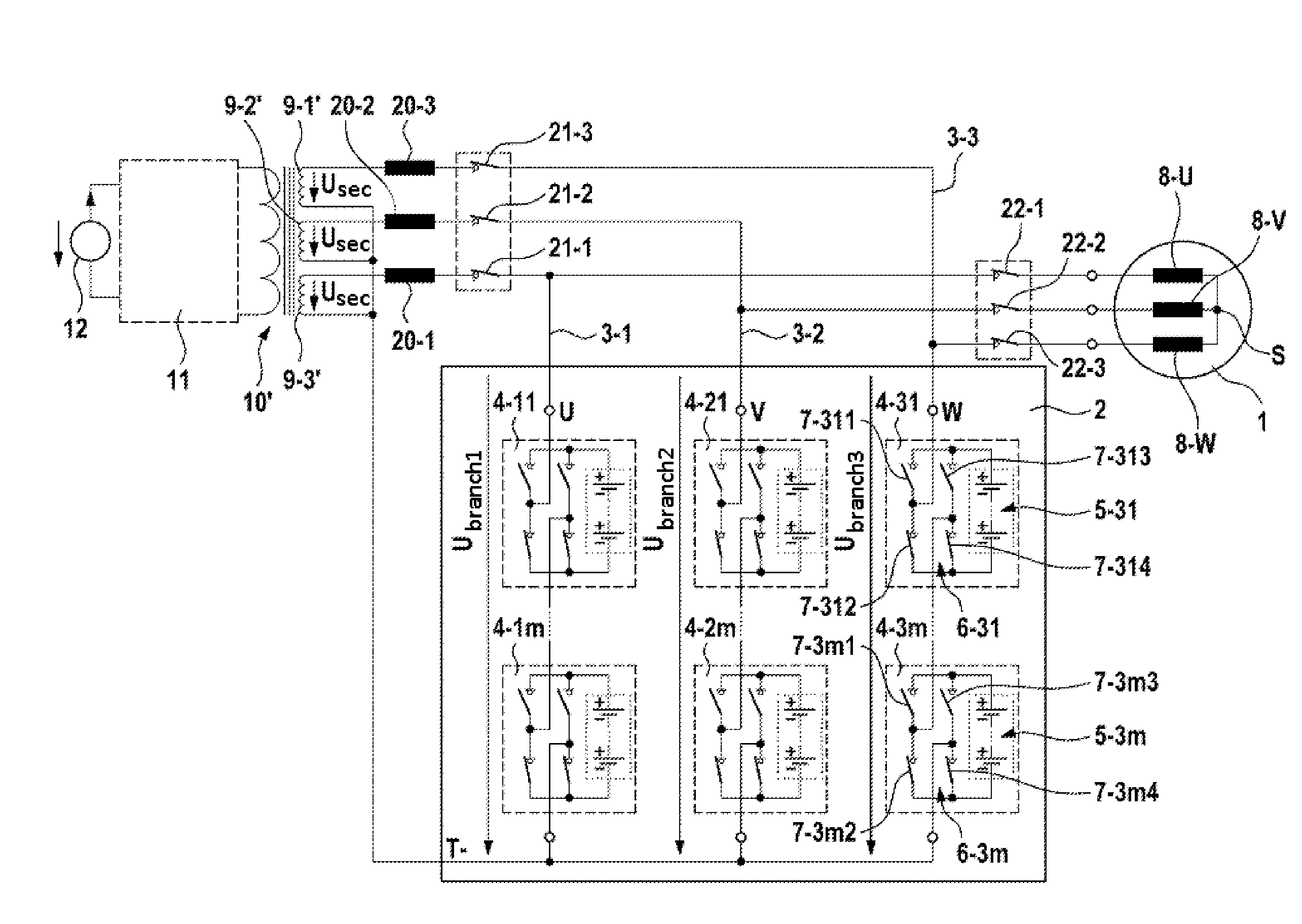
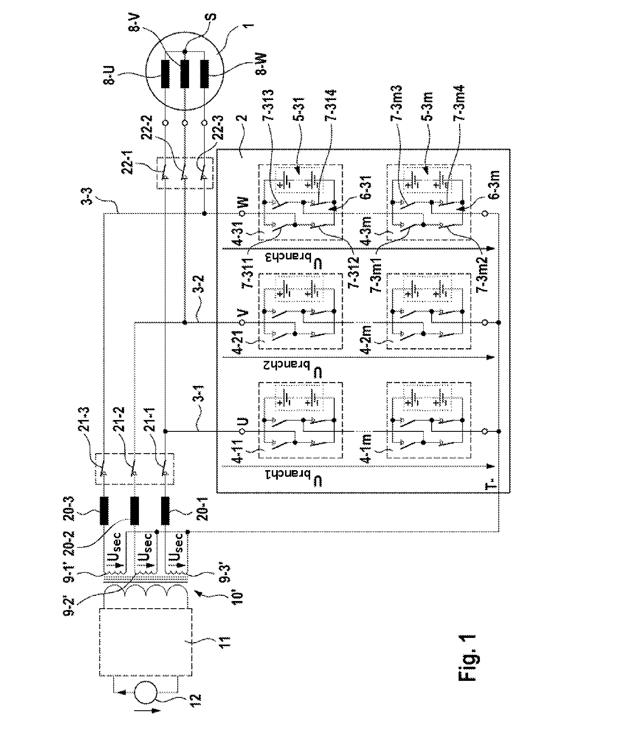
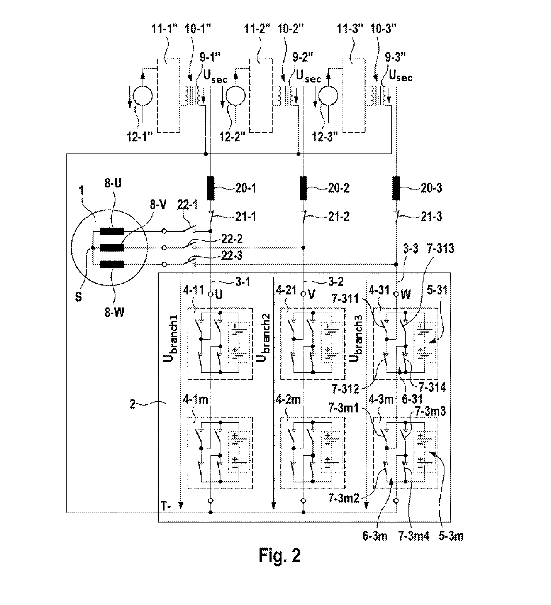
[0018]FIGS. 1 and 2 show schematic illustrations of embodiments of a charging system of the invention. A controllable energy store 2 is connected to a three-phase electrical machine 1. The controllable energy store 2 comprises three energy supply branches 3-1, 3-2 and 3-3, which are connected on one side to a reference potential T- (reference rail), which supplies a low potential in the illustrated embodiments, and on the other side in each case to individual phases U, V and W of the electrical machine 1. Each of the energy supply branches 3-1, 3-2 and 3-3 have m series-connected energy storage modules 4-11 to 4-1m or 4-21 to 4-2m or 4-31 to 4-3m, where m>2. In turn, the energy storage modules 4 comprise in each case a plurality of series-connected electrical energy storage cells, which, for reasons of clarity, are only provided with reference signs 5-31 to 5-3m in the energy supply branch 3-3 connected to the phase W of the electrical machine 1. Furthermore, the energy storage modu...


PUM


Abstract

The invention relates to a system for charging at least one energy storing cell (5) in a controllable energy store (2) that is used to control and supply electric energy to an n-phase electric machine (1), wherein n≧1. The controllable energy store (2) has n parallel energy supply branches (3-1, 3-2, 3-3), each of which has at least two serially connected energy storing modules (4), each said energy storing module comprising at least one electric energy storing cell (5) with a corresponding controllable coupling unit (6). The energy supply branches (3-1, 3-2, 3-3) can be connected to a reference bus (T-), and each energy supply branch can be connected to a phase (U, V, W) of the electric machine (1). The coupling units (6) bridge the respective corresponding energy storing cells (5) or connect same into the respective energy supply branch (3-1, 3-2, 3-3) dependent on control signals. The aim of the invention is to allow at least one energy storing cell (5) to be charged. This is achieved in that each energy supply branch (3-1, 3-2, 3-3) can be connected to and separated from a secondary side (9-1′; 9-1″; 9-2′; 9-2″; 9-3′; 9-3″) of a charging transformer (10′; 10-1″; 10-2″; 10-3″) by a respective controllable switching element (21-1; 21-2; 21-3), an additional charging inductor (20-1; 20-2; 20-3) being arranged in each connecting line between the energy supply branches (3-1, 3-2, 3-3) and the secondary sides (9-1′; 9-1″; 9-2′; 9-2″; 9-3′; 9-3″) of the charging transformer (10′; 10-1″; 10-2″; 10-3″).

Description

BACKGROUND OF THE INVENTION[0001]The invention relates to a system for charging an energy store and to a method for operating the charging system of the invention.[0002]The trend is that in the future electronic systems which combine new energy store technologies with electrical drive technology will be used increasingly both in stationary applications, such as wind power plants, and in vehicles, such as hybrid or electric vehicles. In conventional applications, an electrical machine which is in the form of a polyphase machine, for example, is controlled via a converter in the form of an inverter. A characteristic feature of such systems is a so-called DC voltage intermediate circuit, via which an energy store, generally a battery, is connected to the DC voltage side of the inverter. In order to be able to meet the requirements for a respective application placed on power and energy, a plurality of battery cells are connected in series. Since the current provided by such an energy s...

Claims


Application Information

Patent Timeline
Patent Type & Authority Applications(United States)
IPC IPC(8): H02J7/02
CPCH02J7/022H02J7/0024H02J7/1492H02P27/06Y02T10/92B60L50/51H02J2207/20H02J2207/40H02J2310/48H02J2300/28H02J7/0025Y02T10/64Y02T10/70H02M7/4835H02M7/49H02J7/02Y02E10/76
Inventor FEUERSTACK, PETERWEISSENBORN, ERIKKESSLER, MARTIN
Owner ROBERT BOSCH GMBH
Why Eureka
Try Eureka