

Defoaming method and defoaming apparatus
a defoaming apparatus and foaming technology, applied in the direction of instruments, separation processes, packaging goods, etc., can solve the problems of reducing the oxygen content in the headspace, unable to remove the oxygen in the foam, and insufficient time, so as to reduce the cost, facilitate manufacturing, and simplify the structure of the acoustic waveguide
Inactive Publication Date: 2013-12-12
TOYO SEIKAN GRP HLDG LTD
View PDF3 Cites 7 Cited by
- Summary
- Abstract
- Description
- Claims
- Application Information
AI Technical Summary
Benefits of technology
The present invention provides a method and apparatus for efficient defoaming in a way that prevents contamination and improves the use of pulsed sound waves generated by the shock of laser-induced breakdown of pulsed laser beam. The technical effects are improved efficiency and effectiveness in defoaming, as well as prevention of contamination.
Problems solved by technology
In addition, a sufficient time cannot be taken until the foam disappears.
Further, the oxygen in the foam cannot be removed by gas displacement in the headspace, which hinders the reduction of the oxygen content in the headspace.
However, the taste of the contents such as beverages may be affected.
For this reason, a long time is required for defoaming, so that defoaming cannot be performed at a high speed.
Further, the foam in the vicinity of the inner circumferential surface of the container cannot also be broken effectively.
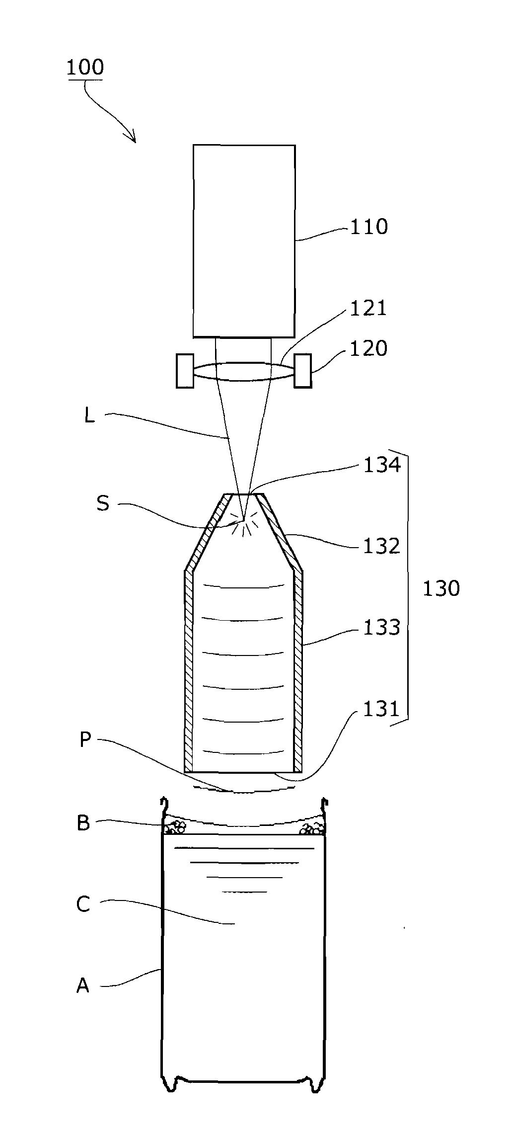
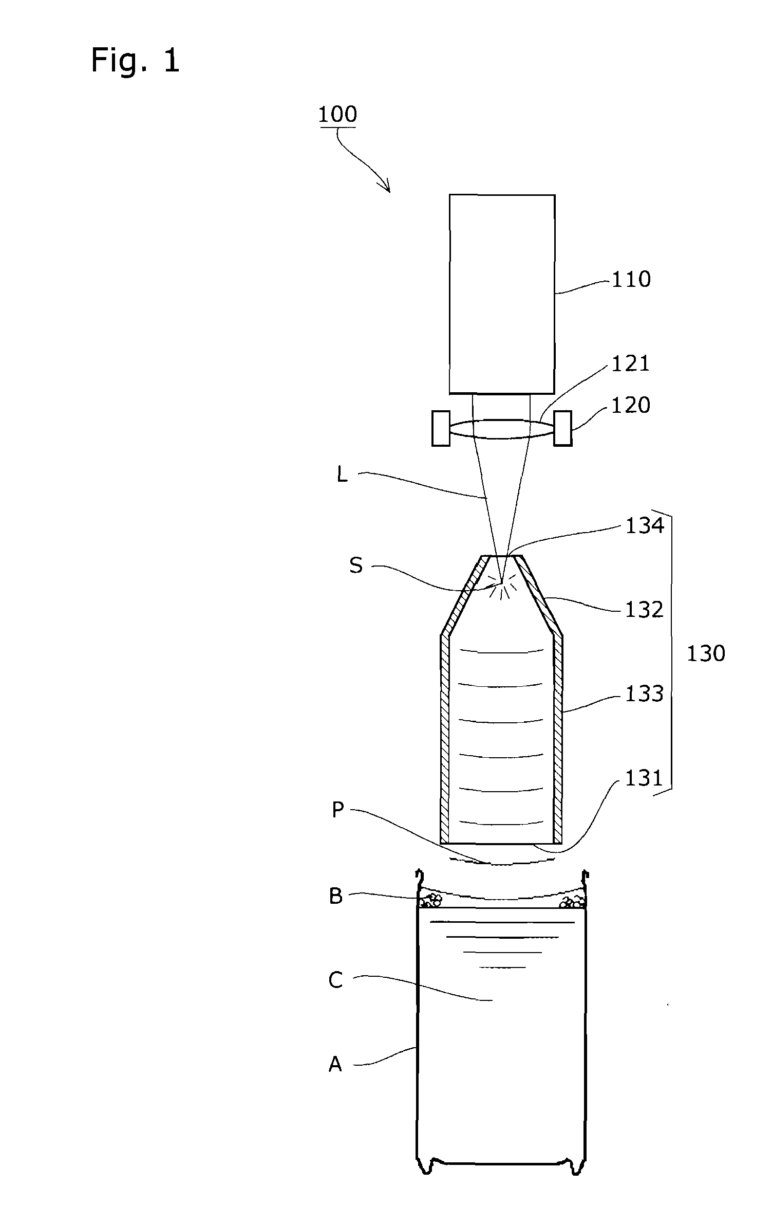
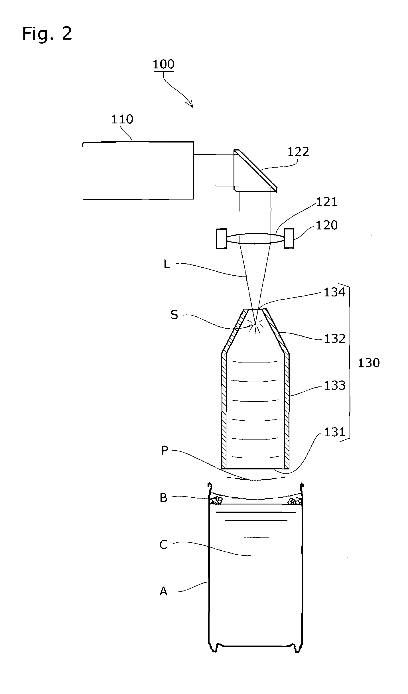
Thus, the pulsed sound waves with a strong change in pressure propagate as spherical waves from a sound source, and destroy the foam for defoaming.
Thus, the foam in the vicinity of the inner circumferential surface of the container difficult to break with a conventional method can also be effectively broken.
However, the shock on the liquid surface of a beverage or the like is large.
Accordingly, droplets are dispersed to be deposited on an apparatus, or a condensing optical system such as a condensing lens, thereby causing contamination.
This results in the reduction of the laser beam condensing property.
The pulsed sound waves are generated in the free space, and propagate as spherical waves, and the pulsed sound waves are only partially involved in defoaming, resulting in the reduction of the defoaming efficiency.
Method used
View moreImage
Smart ImageViewing Examples

Examples
experiment 1
[0094] laser beam incident hole inner diameter, opening inner diameter 40 mm.
[0095]Experiments 2 to 7: laser beam incident hole inner diameter 10 mm, opening inner diameter 40 mm.
(3) Inner Circumferential Surface Shape
[0096]Experiment 1: straight tube.
experiment 2
[0097] taper tube including a tapered part having a taper angle from the laser beam incident hole of 150° (4 mm in height) formed therein.
experiment 3
[0098] taper tube including a tapered part having a taper angle from the laser beam incident hole of 120° (8.7 mm in height) formed therein.
Login to View More PUM
| Property | Measurement | Unit |
|---|---|---|
| Angle | aaaaa | aaaaa |
| Angle | aaaaa | aaaaa |
| Angle | aaaaa | aaaaa |
Abstract
The objective of the present invention is to obtain an effective defoaming effect by directing a pulsed sound wave generated by shock caused by laser-induced breakdown to a liquid surface using an acoustic waveguide. A reflected wave of the pulsed sound wave generated by shock caused by laser-induced breakdown on an inner circumference face of the acoustic waveguide is directed to an opening part of the acoustic waveguide opposed to the liquid surface, and variations in periods of time in which the reflected wave in each travelling direction arrives at the opening part are reduced.
Description
TECHNICAL FIELD[0001]The present invention relates to a defoaming method and a defoaming apparatus suitable for breaking foam on the liquid surface, more particularly, for breaking foam generated when various containers such as metal cans, cups made of plastic, tray-like containers, PET bottles, bottle cans, or glass bottles are filled with the contents such as beverages.BACKGROUND ART[0002]In a filling step of various packaged beverages (such as canned beverages, beverages in PET bottles, and bottled beverages), generally, the beverage is filled from above into a container disposed vertically in a filling machine, and then, the container is sealed by a lid or a cap by means of a sealing machine (such as a seamer or a capper). Then, as the important factor for keeping the beverage quality and improving the flavor, there is the reduction of the residual oxygen content in the sealed container. Particularly, it is important to remove oxygen from the headspace in the container. In order...
Claims
Login to View More Application Information
Patent Timeline
 IPC IPC(8): B01D19/02
CPCB01D19/02B01D19/0073B67C3/22B65B3/22G10K15/046
InventorTATSUMI, YOSHITAKAKIMURA, YOSHIHIKONAKANE, YUUYAMORITA, YOSHIYUKI
OwnerTOYO SEIKAN GRP HLDG LTD