Methods and apparatus for creating large energy storage mass through the collection and use of warmed water

a large energy storage and mass technology, applied in the field of renewable energy, can solve the problems of inherently polluting fossil fuel procurement, inability to meet the needs of large-scale production,

Inactive Publication Date: 2013-12-12
HENDRICKSON JR REYNOLD
View PDF19 Cites 9 Cited by
  • Summary
  • Abstract
  • Description
  • Claims
  • Application Information

AI Technical Summary

Benefits of technology

[0015]The present invention is an apparatus and method to store ambient environmental energy in warm or hot water, on a large enough scale, that it becomes practical as part of a renewable energy system for residential, office, and industrial uses. It is ...

Problems solved by technology

Fossil fuels pollute and are largely responsible for deleterious Global Warming, the greenhouse effects.
Additionally, pollution from fossil fuels makes air in many major cities, such as Mexico City, Beijing, and Los Angeles, unhealthy to breathe for many people.
The procurement of fossil fuels, whether in mining coal or drilling for petroleum, is inherently polluting.
Mountaintop removal for coal and fracking for natural gas both contaminate ground water, endangering the life and health of those nearby.
Drilling for petroleum is also fraught with hazard; witness the BP drilling catastrophe in the Gulf of Mexico in 2010 or the grounding of the Exxon Valdez in 1989.
Fossil fuels give undue influence to governments who control large exportable quantities.
Many oil-exporting Middle East regimes are openly hostile to and contemptuous of the United States, notably Iran.
Many other autocratic “friendly” regimes such as Saudi Arabia and Kuwait are clearly unstable and vulnerable, in light of the Arab Spring.
Even without these serious national security issues, to the extent that fossil fuels are imported needlessly, a nation exports its wealth, needlessly.
Fossil fuels are also becoming increasingly scarce, meaning that their price is rising.
This has led to volatility in the oil markets, with the cost of a barrel of oil peaking at $140 in 2008.
Since then, the price for crude oil has varied from a low of $70 per barrel to a high of $110 per barrel; such swings...

Method used


Image

  • Methods and apparatus for creating large energy storage mass through the collection and use of warmed water
  • Methods and apparatus for creating large energy storage mass through the collection and use of warmed water
  • Methods and apparatus for creating large energy storage mass through the collection and use of warmed water

Examples


Embodiment Construction

[0023]The detailed description is intended to illustrate the present invention, without, in any way, limiting its scope.

[0024]The invention is a component for use in a renewable energy system, applicable to residential, commercial and industrial buildings. The system uses, as one of its components, a large-scale energy storage system. The system is a large-scale energy storage in a warm or hot water thermal mass, and is designed with due consideration of the climate, terrain, zoning, property size, and installation cost.

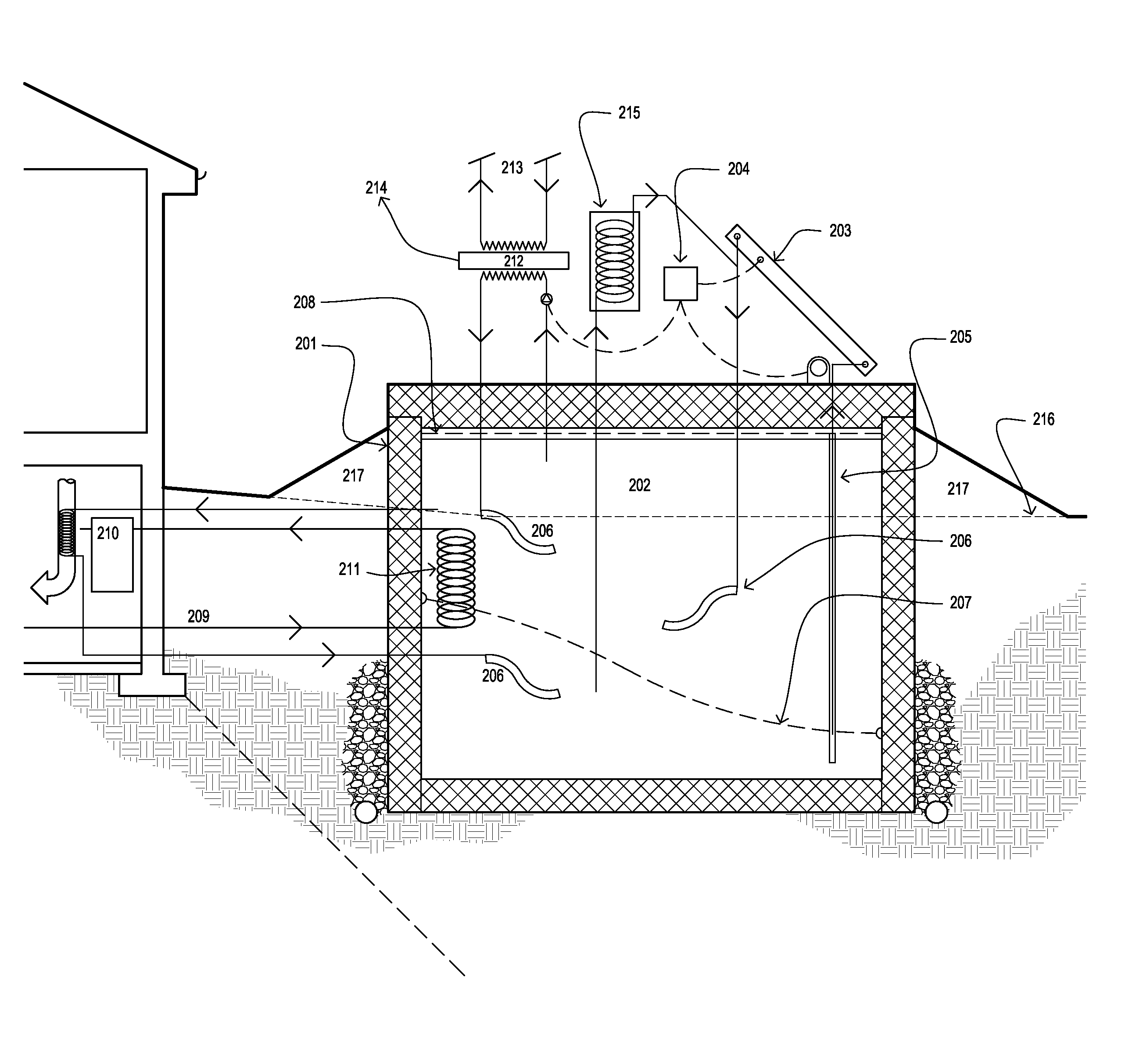
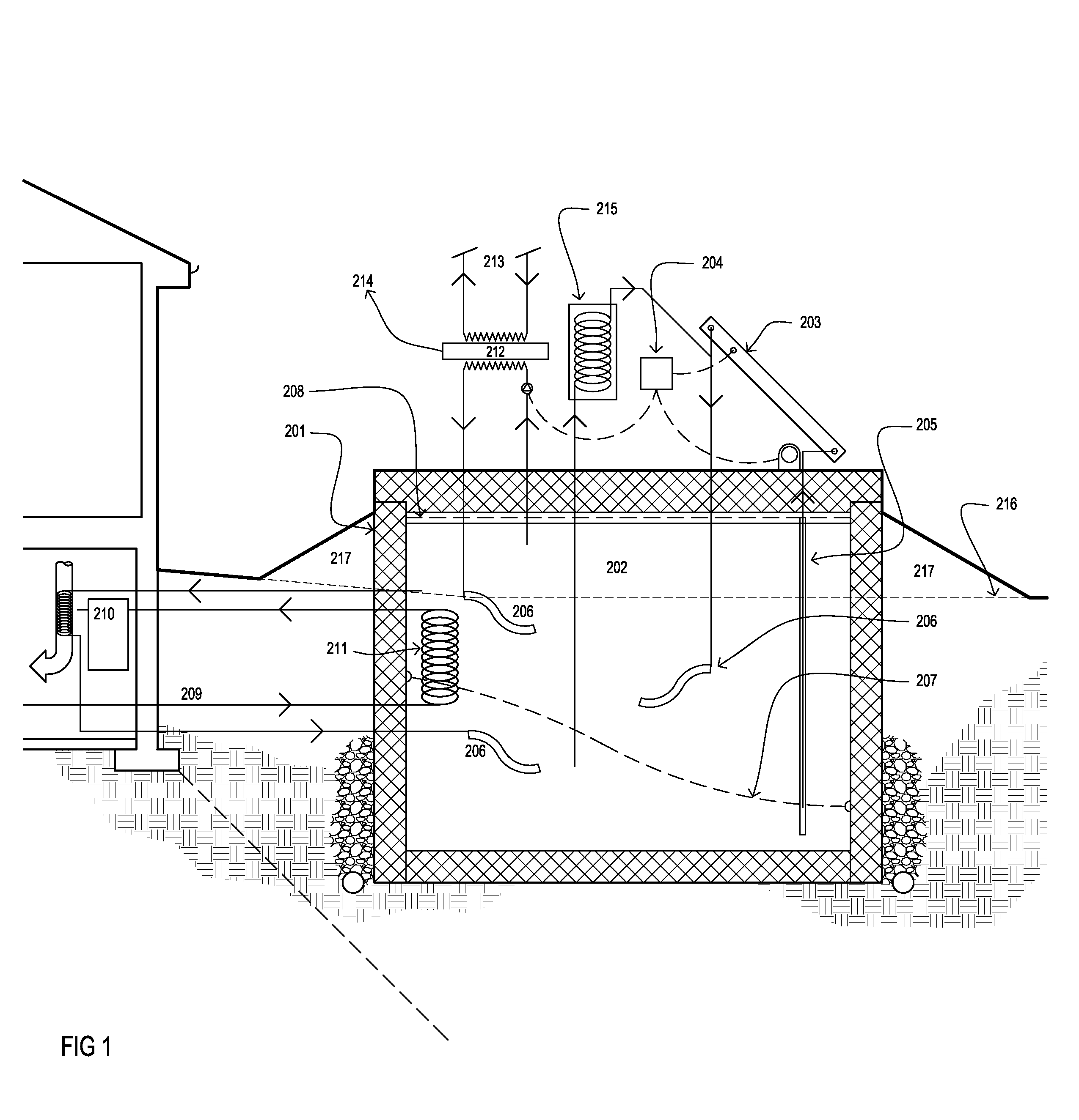
[0025]FIG. 1 shows a method and system for storing warm thermal. The large thermal mass 202 is a liquid medium. In the preferred embodiment, the large thermal mass 202 is water. The large thermal mass 202 is contained within a storage container 201. The storage container 201 is characteristically built in a advantageous method. For example, the storage container 201 can have an outer structural wall of steel, concrete or rammed earth; a plurality of intermediate insu...


PUM


Abstract

A system for heating and supplying electricity to residential, commercial, and industrial buildings using renewable energy that is stored, at little or no incremental cost, in a large mass of warm or hot water. The large thermal mass is sized based on the building. Thermal energy from a number of sources, including, but not limited to renewable energy panels, waste heat, and flue gas, are used to provide heat to the large thermal mass.

Description

FIELD OF INVENTION[0001]This invention relates to the field of renewable energy. Specifically, this invention relates to the large-scale creation and storage of water, which is warmer than the ambient environmental conditions, using renewable heat sources.BACKGROUND OF INVENTION[0002]Currently, most of the world's economies are reliant heavily on fossil fuels. Fossil fuels have many drawbacks. Fossil fuels pollute and are largely responsible for deleterious Global Warming, the greenhouse effects. Additionally, pollution from fossil fuels makes air in many major cities, such as Mexico City, Beijing, and Los Angeles, unhealthy to breathe for many people. The procurement of fossil fuels, whether in mining coal or drilling for petroleum, is inherently polluting. Mountaintop removal for coal and fracking for natural gas both contaminate ground water, endangering the life and health of those nearby. Drilling for petroleum is also fraught with hazard; witness the BP drilling catastrophe in...

Claims


Application Information

Patent Timeline
IPC IPC(8): F24J2/00F24D18/00
CPCF24J2/0007Y02B10/20F24D11/003F28D20/0043F28D20/021F24D11/005F24D17/0047F24D2200/14F24D2200/18F24D2200/26Y02B10/70Y02E70/30Y02E10/47F24S30/422F24S20/70Y02B30/18F24S20/61Y02E60/14Y02P80/20F24D18/00F24D2103/17F24D2103/13F24D2101/60F24D2101/10F24D2101/80Y02E10/44
Inventor HENDRICKSON, JR., REYNOLD
Owner HENDRICKSON JR REYNOLD
Why Eureka
Try Eureka