

Compound, scintillator, and radiation detector
a scintillator and radiation detector technology, applied in the direction of conversion screens, instruments, manufacturing tools, etc., can solve the problem of insufficient intensity of light received when light emitted from the mixed crystal is received on the photoelectric conversion element,
- Summary
- Abstract
- Description
- Claims
- Application Information
AI Technical Summary
Benefits of technology
Problems solved by technology
Method used
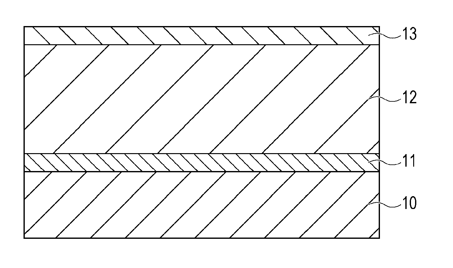
Image

Examples
first embodiment
[0013]In this embodiment, a compound represented by the general formula Cs3Cu2[I1-xClx]5 will be described. In the compound, the value of x representing the proportion of Cl with respect to the sum of I and Cl, which are halogen elements, is 0.71 or more and 0.79 or less, i.e., 0.71≦x≦0.79. To begin with, the range of the proportion x will be described.
[0014]Cs3Cu2I5 corresponds to a compound represented by the foregoing general formula when the proportion x=0. Cs3Cu2Cl5 corresponds to a compound represented by the foregoing general formula when the proportion x=1. They are known materials and have substantially the same crystal structure. However, Cs3Cu2[I1-xClx]5 (0<x<1) is not yet studied or reported.
[0015]The inventors have found that when the range of x in the foregoing general formula satisfies 0.71 or more and 0.79 or less, i.e., 0.71≦x≦0.79 is satisfied, a crystal transparent to visible light is obtained.
[0016]The crystal transparent to visible light has high transparency to...
second embodiment
[0020]In this embodiment, a compound represented by the general formula Cs3Cu2[I1-xClx]5, wherein x represents 0.75, and a method for producing a scintillator including the compound will be exemplified.
[0021]Powder materials of 25 mol % of cesium iodide (CsI), 35 mol % of cesium chloride (CsCl), and 40 mol % of copper chloride (CuCl) were weighed and mixed together to provide a total of 10 g of a powder mixture to be formed into Cs3Cu2[I1.25Cl3.75] (x=0.75).
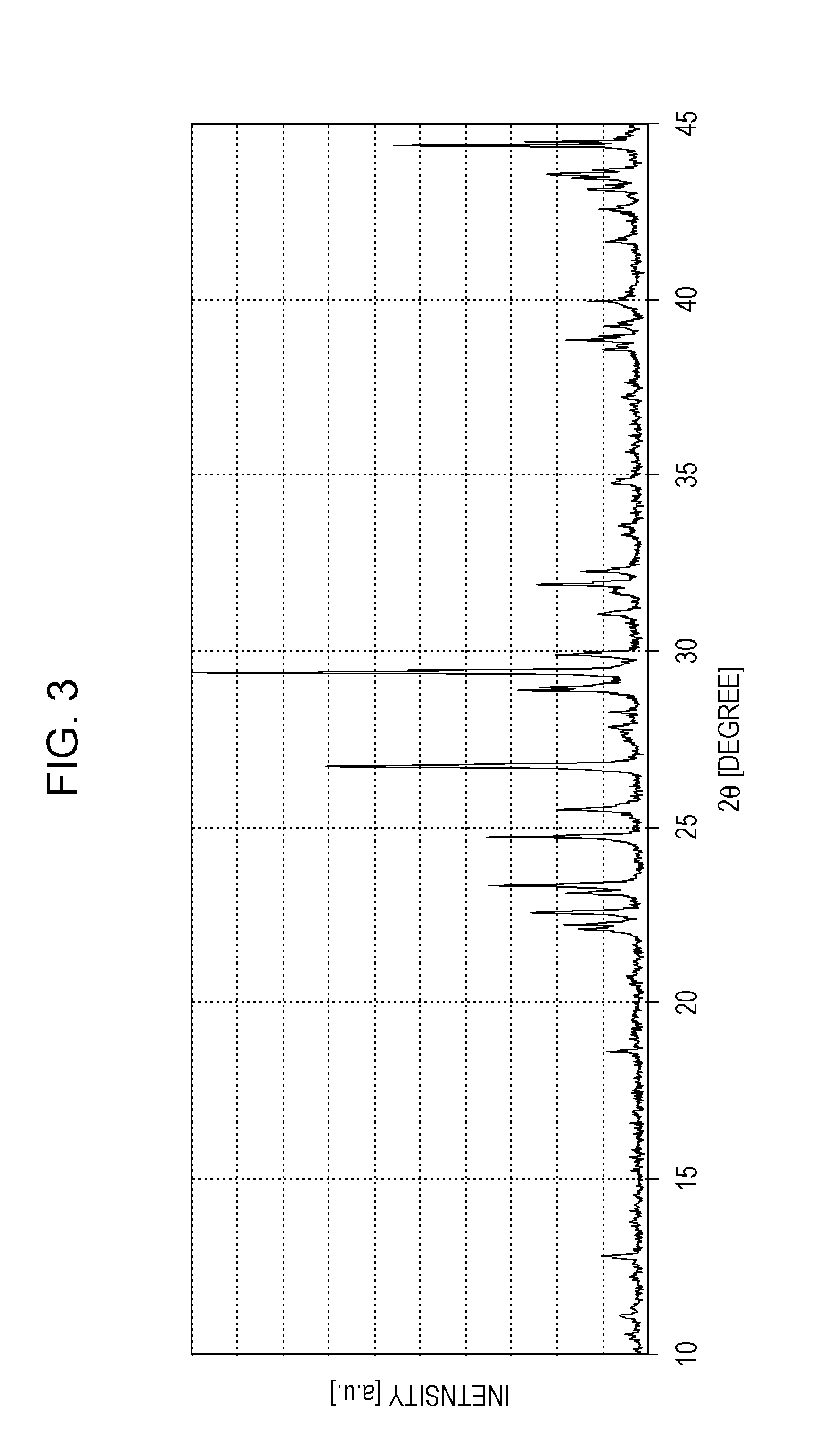
[0022]The powder mixture was sealed in the silica tube under vacuum and then melted at 600° C. for 30 minutes to form a molten material. The temperature was lowered from 600° C. to room temperature at 20° C. per hour with a temperature gradient created along the silica tube, thereby forming a solid product composed of a compound represented by Cs3Cu2[I1.25Cl3.75] (x=0.75). The solid product was taken from the silica tube. The resulting transparent solid product (sample) was subjected to optical microscopic observation and powder ...
third embodiment
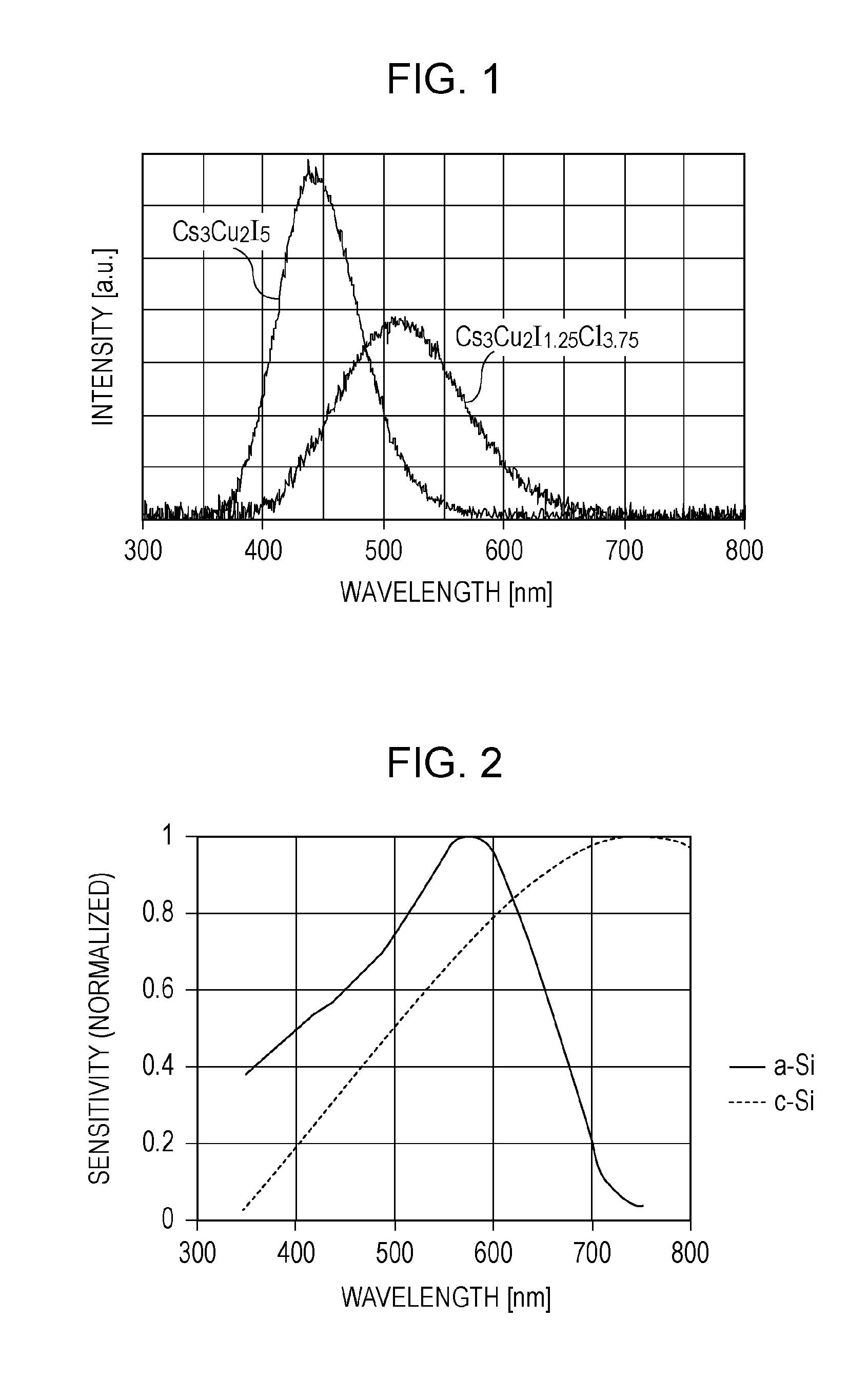
[0032]This embodiment states that when light is emitted from a compound under X-ray excitation, the compound according to the second embodiment exhibits a high intensity of the light received on a photoelectric conversion element (intensity of light received), compared with the Cs3Cu2I5 mixed crystal.
[0033]In this specification, the intensity of light received indicates a value obtained by finding the product of the emission spectrum and the sensitivity curve of the photoelectric conversion element for each wavelength and adding these products.
[0034]First, the emission spectrum will be described below. As described in the second embodiment, FIG. 1 illustrates the emission spectra of Cs3Cu2[I1.25Cl3.75] (x=0.75) and the Cs3Cu2I5 mixed crystal under X-ray excitation. Here, these emission spectra are normalized to the cross-sectional area of each sample. It is thus possible to compare the emission intensity of the foregoing compound with that of the mixed crystal for each wavelength. T...
PUM
| Property | Measurement | Unit |
|---|---|---|
| Percent by mass | aaaaa | aaaaa |
| Percent by mass | aaaaa | aaaaa |
| Weight | aaaaa | aaaaa |
Abstract
Description
Claims
Application Information