Biosensor array formed by junctions of functionalized electrodes

a functional electrode and biosensor technology, applied in the field of biomolecule detection, can solve the problems of only being able to detect low gene expression levels, wasting manpower, time, material consumption and data processing power, and unable to detect transcript isoforms, so as to simplify the process of forming a sensor array

Active Publication Date: 2013-12-12
LEXOGEN GMBH
View PDF1 Cites 24 Cited by
  • Summary
  • Abstract
  • Description
  • Claims
  • Application Information

AI Technical Summary

Benefits of technology

[0020]The main objective of the invention is to provide an improved sensor array with surface regions of differently functionalized surfaces and to simplify the process of forming a sensor array with different organic sensor compounds on its surface.

Problems solved by technology

Despite obvious advantages like hypothesis neutrality, which means that this method can be applied without pre-knowledge, several drawbacks are evident.
First, NGS systems and kits are costly in terms of manpower, time, material consumption and data processing power.
Second, detection of low gene expression levels is only possible if samples are sequenced to extreme depth, which means in turn that common transcripts are read manifold before rare reads become visible.
Third, the detection of transcript isoforms remains probabilistic and heavily relies on a-priori information.
It contributes to the reduced applicability of NGS methods in the analysis of highly complex samples.
One major drawback is their lack of discriminatory power to distinguish cognate sequences, e.g. splice variants.
Cross-hybridizations are common and blur the results.
However, the number of targeted analytes is much too small to investigate complex transcriptomes in depth.
The two primers are immobilized to a single sensor surface either as a mixture or sequentially to form a mixed layer of primers at the surface which becomes very challenging for larger arrays.
One difficulty results from the fact that different sites of the analyte molecule reacts with the very same surface.
The production of said gaps is technologically difficult but feasible.
But, such kind of individual conductor modification is challenging when it comes to nanometer dimensions.
As the number of electrically conducting but different materials in line with a specific and effective binding chemistry is limited, such an approach is not applicable for building large arrays.
Such method is unsuitable to build complex sensor arrays because it is very time consuming and prone to cross-contamination when once functionalized capture probes must be stripped to obtain pristine surfaces again with all previously bound molecules being physically removed before introducing the new species.
This approach suffers from low scalability.
Thus, the double sided functionalizing of nanogap capacitor arrays with different biomolecules remains an unsolved issue.

Method used


Image

  • Biosensor array formed by junctions of functionalized electrodes
  • Biosensor array formed by junctions of functionalized electrodes
  • Biosensor array formed by junctions of functionalized electrodes

Examples


first preferred embodiment

Sensor Arrays with Conducting Sensor Half-Elements which are Supported by Plates and Contain DNA Sensor Compounds

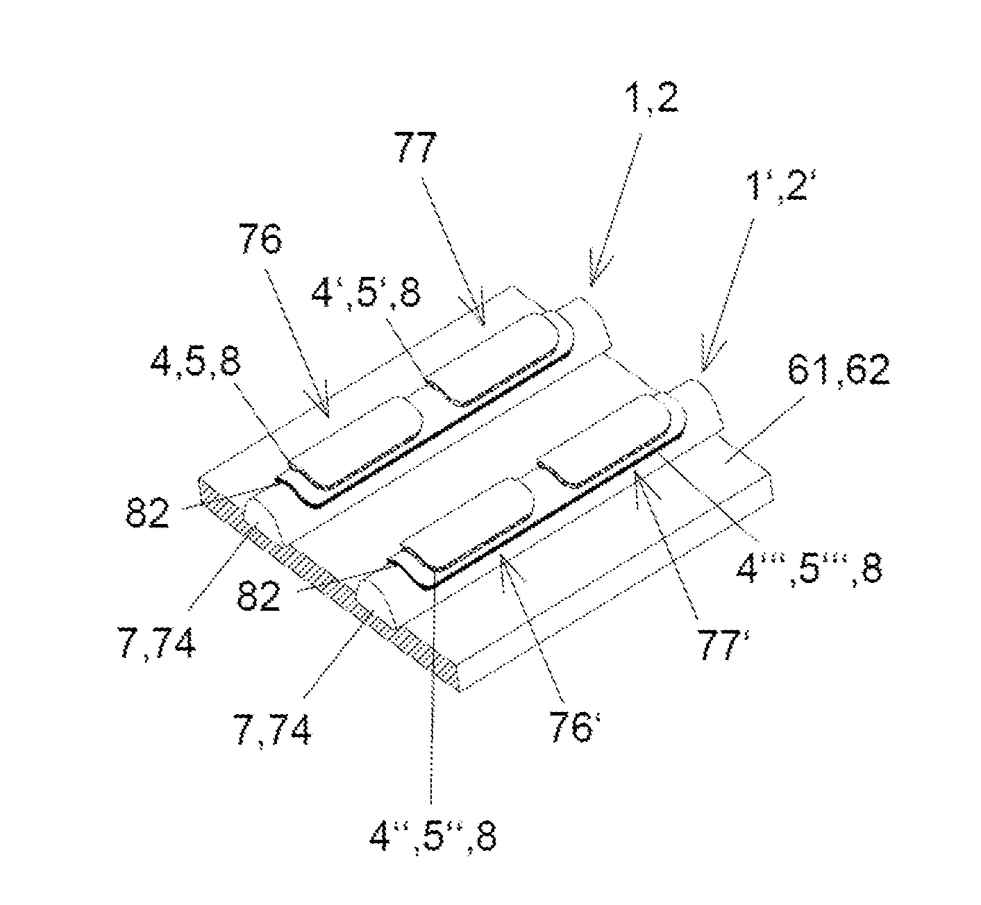
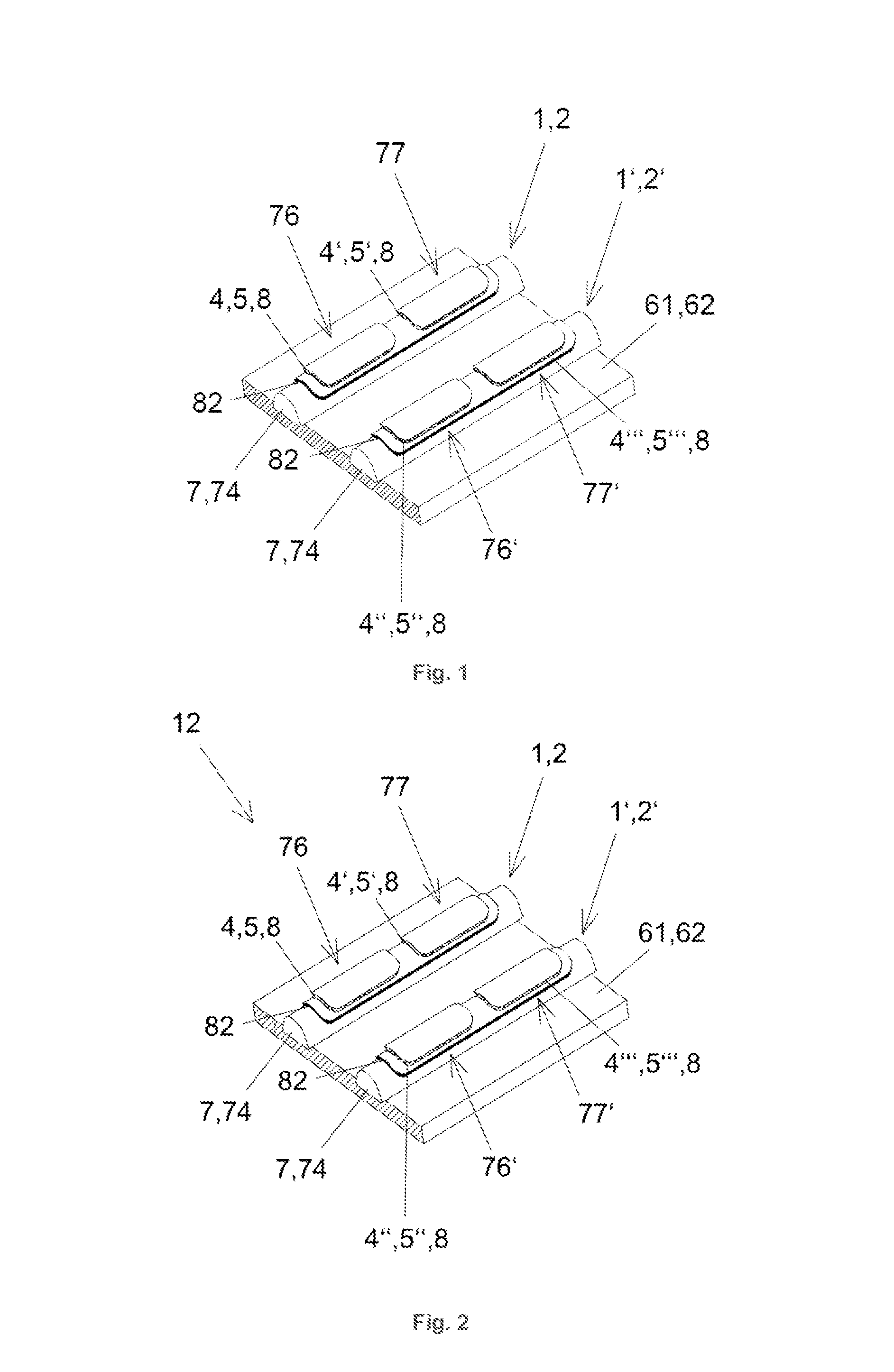
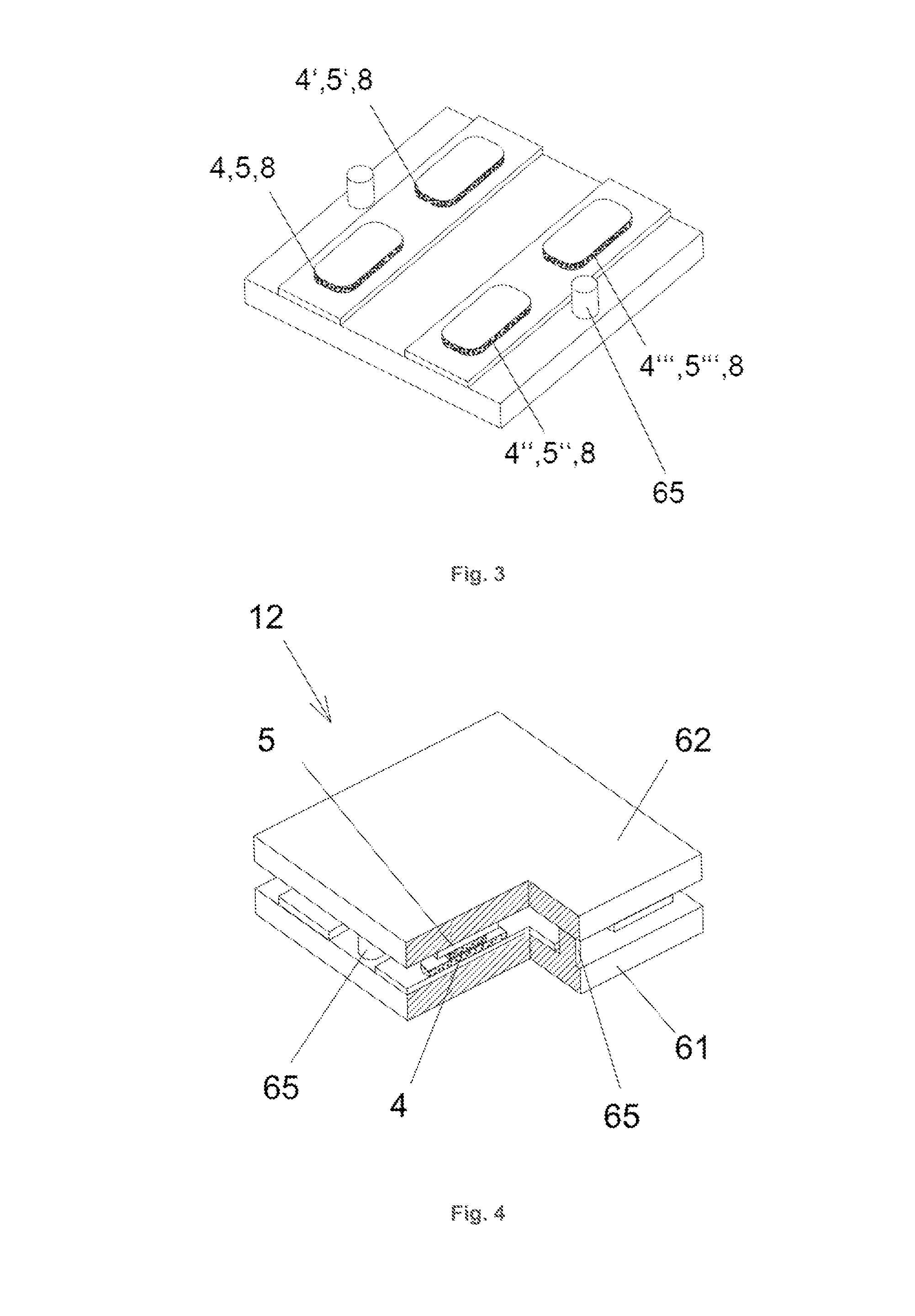
[0094]The first preferred embodiment is shown in FIGS. 1 and 2 and describes a sensor array 12 with linear conducting sensor half elements 1, 2, which are supported by two common carrier 61, 62 formed by plates. In this preferred embodiment of the invention, the sensor compounds are comprised of or comprise oligonucleotides. The analyte entering the measurement cell (not depicted), which surrounds the sensor array 12, is a mixture of cDNA molecules. The junction areas 31 are part of elongated spots, which are arranged along rows and columns of sensor half elements 1, 2. All sensor half elements 1, 2 are arranged in parallel on their respective common carriers 61, 62. One common carrier 61, 62 is depicted in FIG. 1. The functionalization of the sensor half elements 1, 2 occurred before assembling the common carriers 61, 62. During assembly the first common carrier 61 and t...

second preferred embodiment

Sensor Arrays with Transparent Sensor Half Element Glass Fibers and Polypeptide Sensor Compounds

[0141]The second embodiment of the invention describes a sensor array 12 with straight aligned sensor half elements 1, 2 as shown in FIG. 10 or woven sensor half elements 1, 2 as shown in FIG. 11 which are grouped as row 1 and column elements 2. All sensor half elements 1, 2 are identical except their individual functionalizations. The gap between the sensor half elements 1, 2 is caused by the convexly shaped surface of the sensor half elements 1, 2. The sensor half elements 1, 2 are transparent. An optical readout device 141 detects changes in the gap area 31 of the individual sensors 3. The sensor compounds 4, 5 are polypeptides and polynucleotides. The analyte 9 are polypeptides.

[0142]Sensor Half-Elements and their Functionalization

[0143]Commercially available glass fibers of 20 μm outer diameter were chemically activated by silanization to produce amino-reactive layers with N-hydroxys...

examples

Sensor Half Elements Surface Structuring

[0160]The extent of surface interaction can be enhanced through additional soft matter coatings which are grouped in the category carrier material layer 8. Polymers, in particular gels, are suitable to form a coating which can be squeezed. Such coatings contain binding sites to covalently bind the sensor compounds 4, 5. The junction area 31, i. e. the region between two sensor half elements 1, 2 where molecules 9 under investigation can bind to each of the sensor compounds 4, 5 with two of its binding sites 91, 92, can be increased by using said gels. Dendrimers like polypropylenimine polyamine range from tetramines to tetrahexacontamines and can be chosen to build 3D-like structures with higher interface densities of the sensor compounds 4, 5.

[0161]FIG. 5 presents a sensor half element 1, 2 which is supported by a carrier 7 and coated by an insulating layer 82. The different sensor compounds 4, 5 are embedded in a carrier material layer 8 and...


PUM

PropertyMeasurementUnit
timeaaaaaaaaaa
angleaaaaaaaaaa
widthaaaaaaaaaa

Abstract

The present invention provides a sensor array device with multiple sensor junctions which have been created through the assembly of two or more differently functionalized surfaces. The functionalizing of the prospective sensor junction areas with sensor compounds occurred when the different surfaces were physically separated from each other before the assembly of the sensor array. By these means, sensor junctions can be built smaller than conventional deposition techniques like printing and photolithography would allow for otherwise. As a consequence, each individual sensor junction contains two potentially different sensor compounds. The sensor array identifies and quantifies different biomolecules.

Description

[0001]The present invention provides a sensor array device with multiple sensor junctions which have been created through the assembly of two or more differently functionalized surfaces. The functionalizing of the prospective sensor junction areas with sensor compounds occurred when the different surfaces were physically separated from each other before the assembly of the sensor array. By these means, sensor junctions can be built smaller than by using conventional deposition techniques like printing and photolithography would allow for otherwise. As a consequence, each individual sensor junction contains two potentially different sensor compounds. The sensor array identifies and quantifies different biomolecules.FIELD OF INVENTION[0002]The present disclosure relates to the detection of biomolecules via dedicated sensor array devices. More specifically, the present disclosure addresses the multiplexed, parallel detection of linear biopolymers such as DNA, RNA or proteins, also addr...

Claims


Application Information

Patent Timeline
Patent Type & Authority Applications(United States)
IPC IPC(8): C12Q1/68
CPCC12Q1/686G01N27/3278C12Q1/6837
Inventor REDA, TORSTENHAGLMUELLER, JAKOBSCHITTER, GEORGSEITZ, ALEXANDER
Owner LEXOGEN GMBH
Why Eureka
Try Eureka