Cooling system in a vehicle

a cooling system and vehicle technology, applied in the direction of engines, mechanical equipment, machines/engines, etc., can solve the problems of not being able to meet the needs of all the coolers and components, affecting the cooling system, and imposing a large cooling effect, so as to increase the cooling system capacity, increase the flow of coolant through the second radiator, and reduce the pressure drop in the fourth line circuit.

Inactive Publication Date: 2013-12-19
SCANIA CV AB
View PDF6 Cites 18 Cited by
  • Summary
  • Abstract
  • Description
  • Claims
  • Application Information

AI Technical Summary

Benefits of technology

[0006]The object of the present invention is to propose a cooling system in a vehicle which makes it possible to cool a large number of components of the vehicle to a low temperature. Another object of the cooling system is that it be capable of coping with momentary peak loads. A further object of the cooling system is that it be capable of preventing ice formation in coolers which contain water vapour.
[0014]According to another embodiment of the invention, the fourth line circuit comprises a bypass line and a valve by which the coolant can be directed past the line with said cooler. Warm coolant will thus be led through the second radiator at times when there is heavy load upon the cooling system and when there is ice formation in a cooler in the form of a charge air cooler or EGR cooler. In such situations it is also of advantage to increase the coolant flow through the second radiator. A bypass line makes it possible for the coolant to be led past the coolers in the fourth line circuit. The pressure drop in the fourth line circuit is thus reduced, thereby increasing the flow of coolant through the second radiator and the capacity of the cooling system.

Problems solved by technology

However, it is not possible for all of the coolers and components which need cooling to a low temperature to be situated in front of the vehicle's radiator in contact with air at the temperature of the surroundings.
If the cooling system is used to cool the hydraulic oil of a hydraulic retarder, it needs to deliver a very large cooling effect when the retarder is activated.
If the retarder is used to brake a vehicle on a long downgrade, the load upon the cooling system may be of long duration, with consequent risk of overheating the coolant in the cooling system.
When the temperature of the surrounding air is lower than 0° C., there is also risk that the precipitated water might freeze to ice within the charge air cooler.
Such ice formation would cause a greater or lesser amount of obstruction of the air flow ducts within the charge air cooler, resulting in a reduced flow of air to the engine and consequent operational malfunctions or stoppages.
If the temperature of the surrounding air is below 0° C., there is also risk that the condensed water might freeze to ice within the EGR cooler.
Such ice formation would cause a greater or lesser amount of obstruction of the exhaust gas flow ducts within the EGR cooler, causing the nitrogen oxides content of the exhaust gases to increase.

Method used


Image

  • Cooling system in a vehicle
  • Cooling system in a vehicle
  • Cooling system in a vehicle

Examples


Embodiment Construction

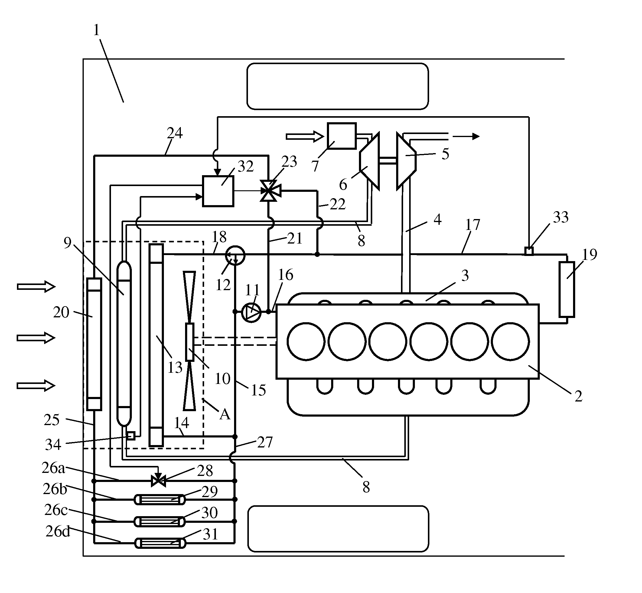
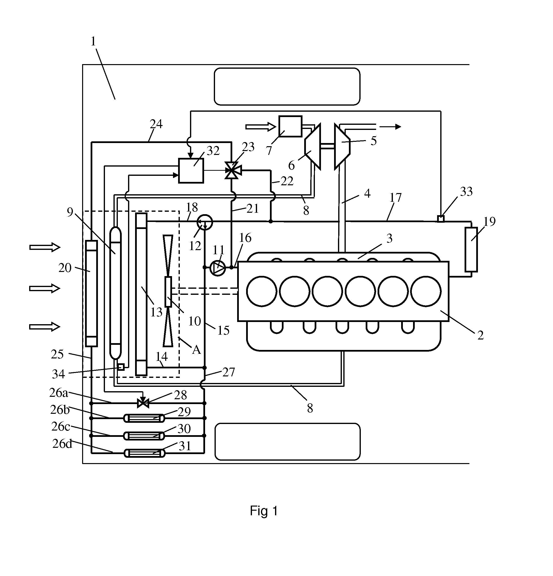
[0018]FIG. 1 depicts a vehicle 1 powered by a supercharged combustion engine 2. The vehicle 1 may be a heavy vehicle powered by a supercharged diesel engine. The exhaust gases from the cylinders of the engine 2 are led via an exhaust manifold 3 to an exhaust line 4. The exhaust gases in the exhaust line 4, which will be at above atmospheric pressure, are led to a turbine 5 of a turbo unit. The turbine 5 is thus provided with driving power which is transferred, via a connection, to a compressor 6. The compressor 6 thereupon compresses the air which is led into an inlet line 8 via an air filter 7. A charge air cooler 9 is provided in the inlet line 8. The charge air cooler 9 is situated in a region A at a front portion of the vehicle 1. The purpose of the charge air cooler 9 is to cool the compressed air before it is led to the engine 2. The compressed air is cooled in the charge air cooler 9 by air which is forced through it by a cooler fan 10 and the draught caused by forward moveme...


PUM


Abstract

A cooling system with a circulating coolant for cooling a combustion engine in a vehicle (1) includes a first radiator (13), a first line circuit (14, 15, 16) which leads coolant from the first radiator (13) to the engine (2); a second line circuit (17, 18) which leads coolant from the engine (2) to the first radiator (13); a second radiator (20) upstream of the first radiator (13) in air flow through radiators; a third line circuit (21, 22, 24) including at least one line (21, 24) to lead coolant from a line (16) in the first line circuit to the second radiator (20), and a fourth line circuit (25, 26a-d, 27) which leads coolant from the second radiator (20) to the first line circuit (15) and which contains at least one cooler (29, 30, 31) for cooling a medium or component of the vehicle (1).

Description

BACKGROUND TO THE INVENTION AND PRIOR ART[0001]The present invention relates to a cooling system in a vehicle according to the preamble of claim 1.[0002]There are quite a number of coolers and components in a vehicle which need cooling to a lower temperature than can be achieved with the coolant in the combustion engine's cooling system. One such cooler is the condenser in an AC system. The condenser is usually situated at the front portion of the vehicle in front of the radiator where it is cooled by air at the temperature of the surroundings. However, it is not possible for all of the coolers and components which need cooling to a low temperature to be situated in front of the vehicle's radiator in contact with air at the temperature of the surroundings. Examples of coolers and components which it is also desirable to cool with a colder medium than the coolant are oil coolers for gearbox oil, oil coolers for servo oil, brake compressors, turbines and electrical control units.[0003...

Claims


Application Information

Patent Timeline
Patent Type & Authority Applications(United States)
IPC IPC(8): F01P7/14
CPCF01P7/14F01P2003/182F01P2060/04F01P2060/08F01P2060/14F02B29/0443F02M26/28Y02T10/12F01P3/20F01P7/16F02B29/04F02M26/27F01P7/165F02B29/0425
Inventor KARDOS, ZOLTANJAHNS, DIETERRUGELAND, OLA
Owner SCANIA CV AB
Why Eureka
Try Eureka