Systems and methods for facilitating oil delivery in digital offset lithographic printing techniques

a technology of offset lithography and oil delivery, which is applied in the direction of lithography, wet duplicator, rotary lithographic machine, etc., can solve the problems of inability to accommodate true high-speed variable data printing process, inability to meet the needs of printing documents, and amortization of the cost of permanently-patterned imaging plates or cylinders over the number of documents produced, so as to improve the storage of releasing materials and improve the effect of thermal absorption of ligh

Active Publication Date: 2014-01-16
XEROX CORP
View PDF2 Cites 3 Cited by
  • Summary
  • Abstract
  • Description
  • Claims
  • Application Information

AI Technical Summary

Benefits of technology

[0015]According to the 714 Application, a reimageable surface is provided on an imaging member, which may be a drum, plate, belt or the like. The reimageable surface may be composed of, for example, a class of materials commonly referred to as silicones, including polydimethylsiloxane (PDMS) among others. The reimageable surface may be formed of a relatively thin layer over a mounting layer, a thickness of the relatively thin layer being selected to balance printing or marking performance, durability and manufacturability.
[0038]Exemplary embodiments may provide a unique design including at least the following (1) A materials composition for a digital offset printing plate containing: (a) a polymeric matrix, and (b) a releasing oil; (2) A multi-layer design that satisfies both specified levels of robustness and sufficient supply of releasing oil; (3) A multi-layer plate that functions as both a reservoir and gate of the releasing material dispersed in the polymeric matrix; (4) A capacity to disperse silicone oil in cross-linked PDMS in fractions as high as 0.75; (5) A thickness and porosity of the upper layer that may be varied to control the amount of releasing material delivered to the surface of the plate; and (6) Sufficient wetting of the plate with the ink and fountain solutions, and improved release of the ink.

Problems solved by technology

These conventional processes are generally not considered amenable to creating and printing a new pattern from one page to the next because, according to known methods, removing and replacing of plates, including on a print cylinder, would be required in order to change images.
For these reasons, conventional lithographic techniques cannot accommodate true high speed variable data printing processes in which the images to be printed change from impression to impression, for example, as in the case of digital printing systems.
Additionally, the cost of the permanently-patterned imaging plates or cylinders is amortized over the number of copies of a document that are produced.
Previously, the number of hurdles to providing variable data printing using lithographic inks appeared insurmountable.
Even the desire to reduce a cost per copy for shorter print runs of the same image presented challenges.
After changing the surface state, fountain solution selectively wets the hydrophilic areas of the programmable surface and, therefore, causes a rejection of the application of ink to these areas.
These switchable coatings, particularly the switchable polymers, tend to be expensive to coat onto a surface and are typically prone to excessive wear.
Also, these switchable coatings tend not to have the capacity to transform between hydrophobic and hydrophilic states in the sub-millisecond time range that would be required to enable high-speed variable data printing using lithographic techniques.
The above-described attempts at implementing variable data lithographic printing still suffered from numerous difficulties.
Shearing forces in the nip between the imaging surface and the ink forming roller can overwhelm any static or dynamic surface energy forces drawing fountain solution to the surface.
A difficulty arises, however, in that these micro-roughened surfaces are difficult to clean by conventional mechanical means such as, for example, by using knife-edge cleaning systems for scraping residual ink from the plate or belt surface.
Additionally, physical contact between the knife and the plate or belt surface results in significant wear.
Once the surface is worn, there is a relatively high cost of replacing a plate or belt.
These cleaning processes, however, tend to increase costs significantly, not only based on the inclusion of required additional subsystems, but also on a potential cost associated with hazardous waste disposal.
Further, to date, these non-contact cleaning processes are of unproven effectiveness.
The difficulty with using smooth surfaces is that the advantage in being able to clean the smooth surface is offset with the reduced ability to retain a hydrophilic coating and printing or marking material as compared to the micro-roughened surface.
So surfaces, therefore, may necessitate employing additional and costly subsystems such as, for example, surface energy conditioning subsystems including a corona discharge apparatus, which themselves can induce wear or damage to the plate or belt surface.
Precise metering of the fountain solution additionally can become more difficult without the presence of correct texture such as, for example, with the micro-roughened surface.
Also, spreading or other lateral movement of the fountain solution on a texture-free surface may compromise ultimate imaging resolution.
Another disadvantage encountered in attempting to modify conventional lithographic systems for variable printing is a relatively low transfer efficiency of the inks off of the imaging plate or belt.
This relatively low efficiency compounds the cleaning problem in that a significant amount of cleaning is required to completely wipe the surface of the plate or belt clean of ink so as to avoid ghosting of one image onto another in variable data printing using a modification of conventional lithographic techniques.
Also, unless the ink can be recycled without contamination, the effective cost of the ink is doubled.
Traditionally, however, it is very difficult to recycle the highly viscous ink, thereby increasing the effective cost of printing and adding costs associated with ink disposal.
Proposed systems fall short in providing sufficiently high transfer ratios to reduce ink waste and the associated costs.

Method used


Image

  • Systems and methods for facilitating oil delivery in digital offset lithographic printing techniques
  • Systems and methods for facilitating oil delivery in digital offset lithographic printing techniques
  • Systems and methods for facilitating oil delivery in digital offset lithographic printing techniques

Examples


Embodiment Construction

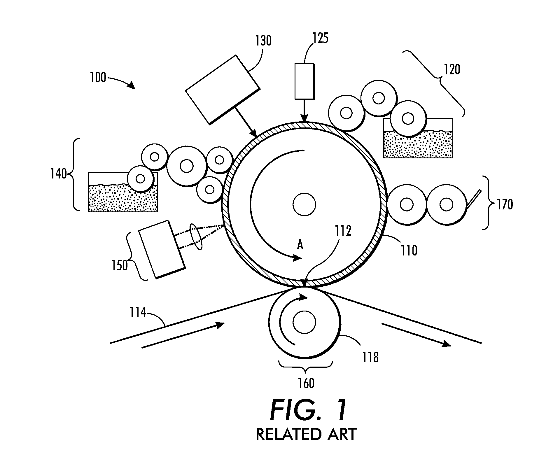
[0014]In order to address the above-identified shortfalls, U.S. patent application Ser. No. 13 / 095,714 (the 714 Application), which is commonly assigned and the disclosure of which is incorporated by reference herein in its entirety, proposes systems and methods for providing variable data lithographic and offset lithographic printing or image receiving medium marking The systems and methods disclosed in the 714 Application are directed to improvements on various aspects of previously-attempted variable data imaging lithographic marking concepts based on variable patterning of fountain solutions to achieve effective truly variable digital data lithographic printing.

[0015]According to the 714 Application, a reimageable surface is provided on an imaging member, which may be a drum, plate, belt or the like. The reimageable surface may be composed of, for example, a class of materials commonly referred to as silicones, including polydimethylsiloxane (PDMS) among others. The reimageable ...


PUM


Abstract

A system and method are provided that incorporate a multi-layer plate configuration for a Digital Offset Plate (DOP) including at least a robust top imaging layer and a bottom layer that acts as a reservoir for the releasing oil in a proposed variable digital offset lithographic architecture. The top imaging layer may contain a small amount of oil (<20%) in a range suitable for allowing a small amount of oil to coat the surface and enable release of the ink. A bottom layer may be larger in volume and contain greater quantities (˜20-75%) of oil. Oil from the reservoir layer may diffuse to and through the top layer when the oil in the top surface layer is depleted in a manner that maintains a supply of oil at the surface. The top layer may act as a gate to maintain a steady flow of oil to the surface.

Description

BACKGROUND[0001]1. Field of Disclosed Subject Matter[0002]This disclosure relates to systems and methods that incorporate a dual layer plate configuration including at least a robust top imaging layer and a bottom layer that acts as a reservoir for the releasing oil in a proposed variable digital offset lithographic architecture.[0003]2. Related Art[0004]Lithography is a common method of printing or marking images on an image receiving medium. In a typical lithographic process, the surface of a print image carrier, which may be a flat plate, cylinder or belt, is formed to have “image regions” of hydrophobic and oleophilic material, and “non-image regions” of a hydrophilic material. The image regions correspond to the areas on the final print on the image receiving medium that are occupied by a printing or marking material such as ink. The non-image regions are the regions corresponding to the areas on the final print on the image receiving medium that are not occupied by the printin...

Claims


Application Information

Patent Timeline
Patent Type & Authority Applications(United States)
IPC IPC(8): B41L11/08B41F1/18B41N3/00
CPCB41C1/10B41N3/006B41C2210/08B41N10/04B41N10/00
Inventor VELLA, SARAH J.MOORLAG, CAROLYN
Owner XEROX CORP
Why Eureka
Try Eureka