Resonant Optical Transducers for In-Situ Gas Detection

a technology of in-situ gas detection and optical transducer, which is applied in the shape and construction of optical resonators, semiconductor lasers, instruments, etc., can solve the problems of poor reliability, limited by the recovery time of pl and a chronic pl quench, and limit the lifetime and complexity of readout syst, so as to enhance the sensitivity of the device, the effect of high quality factor and high sensitivity

Active Publication Date: 2014-01-30
LAWRENCE LIVERMORE NAT SECURITY LLC
View PDF5 Cites 11 Cited by
  • Summary
  • Abstract
  • Description
  • Claims
  • Application Information

AI Technical Summary

Benefits of technology

[0017]Hence, as the desired species is adsorbed onto a state-selective coating within the optical sensor, the coating optical properties are modified by the change in the phase (refractive index) and/or absorption (optical loss) of light as it interacts with the now-modified surface coating. The appropriate use of high-gain optical amplifying media and/or lasers can result in trace-gas sensors with high sensitivity and responsivity, owing to the highly nonlinear dependence of these structures to minute phase and/or amplitude perturbations at or near an oscillation threshold. Resonant cavities with high quality factor (Q), or amplification, can enhance the sensitivity of the devices. The operation wavelength of the devices is, in this case, independent of the gas and only a very small footprint is necessary. Nevertheless, a tunable source pr

Problems solved by technology

The main issues with these systems include the device dimensions, usually in excess of a cubic centimeter, and fiber occlusion, which leads to poor reliability.
Their versatility to detect several gases, e.g., Ox, COx, and NOx, becomes an issue since the level of cross-sensitivity to different gases is

Method used


Image

  • Resonant Optical Transducers for In-Situ Gas Detection
  • Resonant Optical Transducers for In-Situ Gas Detection
  • Resonant Optical Transducers for In-Situ Gas Detection

Examples


Embodiment Construction

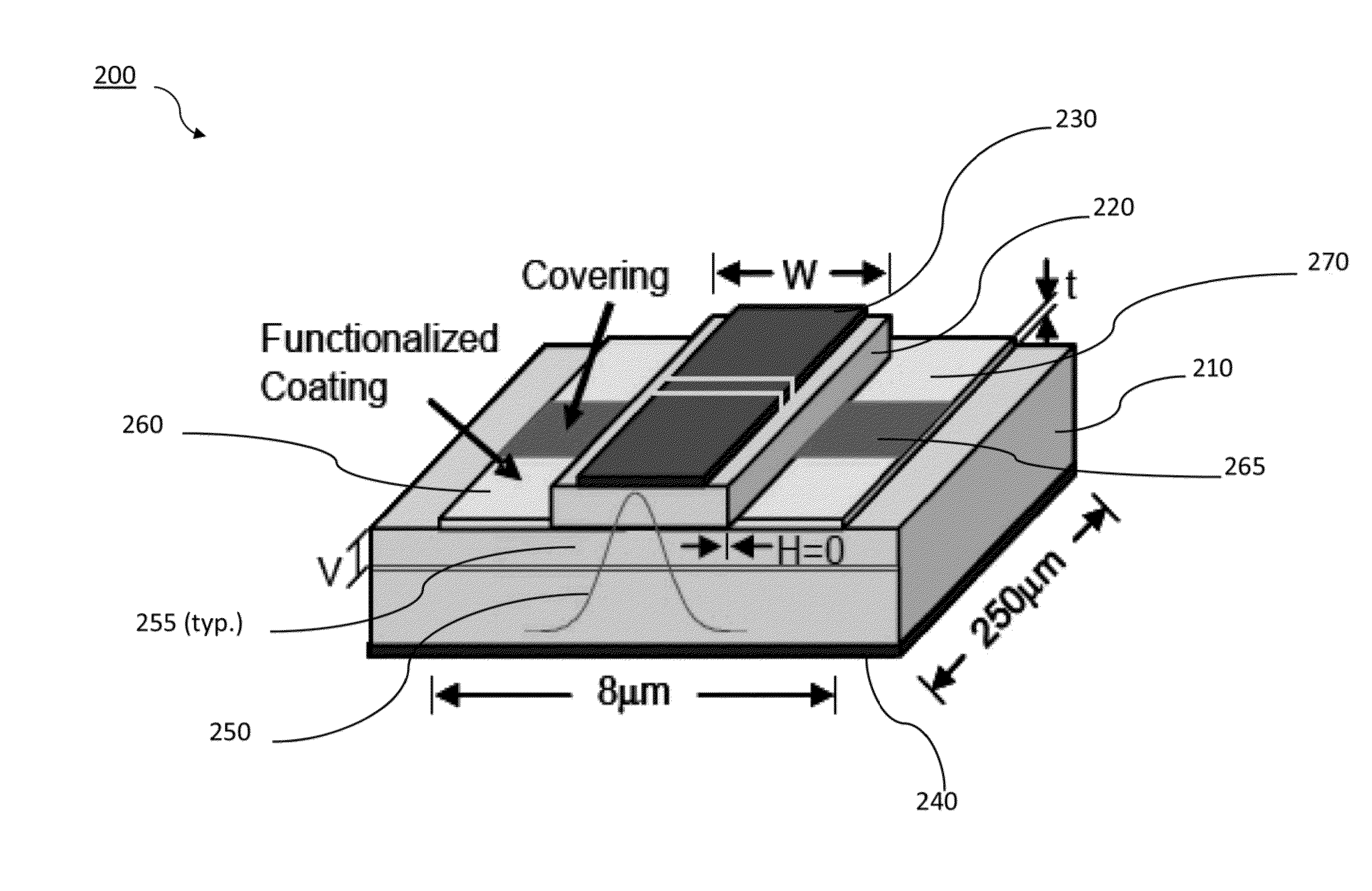
[0032]One embodiment of a present ROT is shown in FIG. 1, the basic structure of which is a semiconductor-based edge-emitting laser, EEL 200. The basic EEL, which is well known in the art, is augmented with a state-selective thin-film functionalized adsorption layer, thereby resulting in the trace-gas sensor. The EEL is comprised of a substrate, 210, upper (gain) guiding ridge layer 220, and top and bottom contacts, 230 and 240, respectively, for biasing. In some cases, the top contact can be partitioned, so that different regions within the laser can possess differing amounts of optical gain or loss. The basic guided-wave optical mode, 250, is confined vertically by the basic waveguide structure and laterally, via gain guiding. The EEL optical cavity consists of a pair of Fresnel reflective air / semiconductor interfaces, 255, formed at the front and rear substrate facets, respectively, normal to the optical axis. The semiconductor materials and structure of the basic laser are well ...


PUM


Abstract

Configurations for in-situ gas detection are provided, and include miniaturized photonic devices, low-optical-loss, guided-wave structures and state-selective adsorption coatings. High quality factor semiconductor resonators have been demonstrated in different configurations, such as micro-disks, micro-rings, micro-toroids, and photonic crystals with the properties of very narrow NIR transmission bands and sensitivity up to 10−9 (change in complex refractive index). The devices are therefore highly sensitive to changes in optical properties to the device parameters and can be tunable to the absorption of the chemical species of interest. Appropriate coatings applied to the device enhance state-specific molecular detection.

Description

CROSS-REFERENCE TO RELATED APPLICATIONS[0001]This application is a Continuation in Part of U.S. patent application Ser. No. 12 / 406,838, titled “Tunable Photonic Cavities for In-Situ Spectroscopic Trace Gas Detection,” filed Mar. 18, 2009, incorporated herein by reference, which claims priority to US. Provisional No. 61 / 037,642, filed Mar. 18, 2008, titled: “Tunable Photonic Cavities for In-Situ Spectroscopic Trace Gas Detection,” incorporated herein by reference and also claims priority to U.S. Provisional No. 61 / 037,645, titled: “Resonant Optical Transducers for In-Situ Gas Detection,” filed Mar. 18, 2008, incorporated herein by reference.STATEMENT REGARDING FEDERALLY SPONSORED RESEARCH OR DEVELOPMENT[0002]The United States Government has rights in this invention pursuant to Contract No. DE-AC52-07NA27344 between the U.S. Department of Energy and Lawrence Livermore National Security, LLC, for the operation of Lawrence Livermore National Laboratory.BACKGROUND OF THE INVENTION[0003]1...

Claims


Application Information

Patent Timeline
IPC IPC(8): H01S5/10
CPCH01S5/10G01N21/39G01N21/774G01N2021/396G01N2021/399G01N2201/06113G01N2201/068H01S3/08059H01S3/1053H01S3/1055H01S5/0028H01S5/18366H01S5/18369H01S2302/00
Inventor BOND, TIZIANA C.COLE, GARRETTGODDARD, LYNFORD
Owner LAWRENCE LIVERMORE NAT SECURITY LLC
Why Eureka
Try Eureka