Apparatus and method for removing contaminants from industrial fluid

a technology of industrial fluid and apparatus, which is applied in the direction of mechanical apparatus, filtration separation, separation process, etc., can solve the problems of difficult to separate water from fuel, alter the ability of fuel to be effectively filtered, and corrosion of engine components, so as to achieve efficient and effective removal of the same from fuel, corrosion, and reduce the effect of corrosion

Inactive Publication Date: 2014-02-06
KAYDON CUSTOM FILTRATION CORP
View PDF2 Cites 41 Cited by
  • Summary
  • Abstract
  • Description
  • Claims
  • Application Information

AI Technical Summary

Benefits of technology

[0015]Yet another aspect of the present invention is an apparatus and method for removing contaminants from liquid fuels, lubricants and other oil based industrial liquid which include a unique coalescer element that is highly resistant to large water content in fuels, including those with surfactants, and is capable of efficiently and effectively removing the same from fuel. The coal

Problems solved by technology

The need to remove free water from such liquids is particularly stringent with liquid hydrocarbon fuel and biodiesel, which are often combined with rich additives, since even a small water content in these fuels results in corrosion of engine components and promotes microbiological growth in the fuel tank.
However, such surfactants make it very difficult to separate the water from the fuel.
The presence of water alters the ability of the fuel to be effectively filtered, due to its physical property changes, and also accelerates fatigue wear in highly stressed mechanical components.
All these factors clearly adversely impact the durability and performance of the engine system.
In general, contaminated fuels harm equipment and interrupt or slow down process operations which results in expensive downtime

Method used


Image

  • Apparatus and method for removing contaminants from industrial fluid
  • Apparatus and method for removing contaminants from industrial fluid
  • Apparatus and method for removing contaminants from industrial fluid

Examples


example 1

Additional Example 1

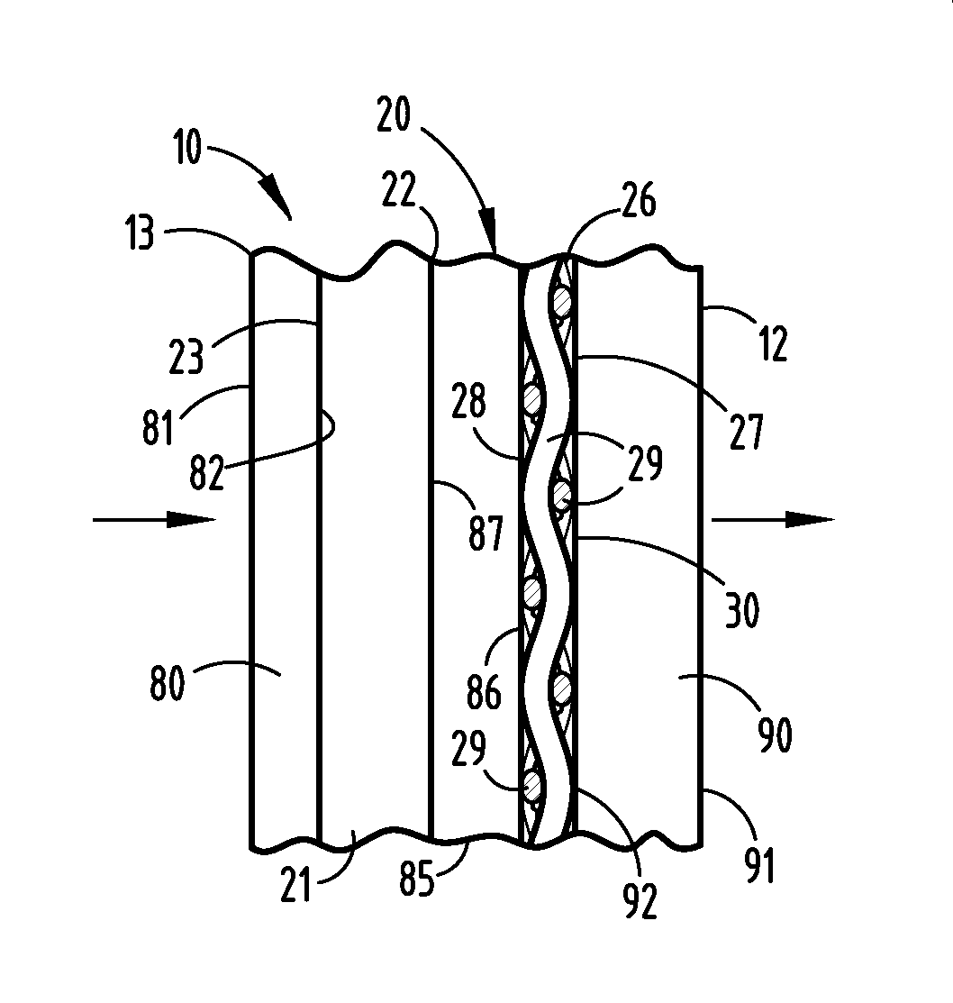
[0110]Additional example one of new pleated coalescence media 20 is made up of two types of fibrous filter media tightly stacked together. One type, at the flow upstream side, is a stack of four layers of non-woven micro fiberglass filter media with two different media structures. More specifically, the first two non-woven media layers are made of media 21, which is non-woven micro fiberglass filter media with a mean flow pore size of 6.5 microns and a water repellency of 5.0 inches of Water Gauge, and the following two non-woven media layers are made of media 85, which is non-woven micro fiberglass filter media with a mean flow pore size of 6.4 microns and a water repellency of 20.0 inches of Water Gauge. The other type, at the flow downstream side, is a pile of two layers of media 26, which is precisely woven hydrophilic monofilament mesh with an opening of 18.0 microns and a thread diameter of 31.0 microns. Furthermore, the above six layers of fibrous filter m...

example 2

Additional Example 2

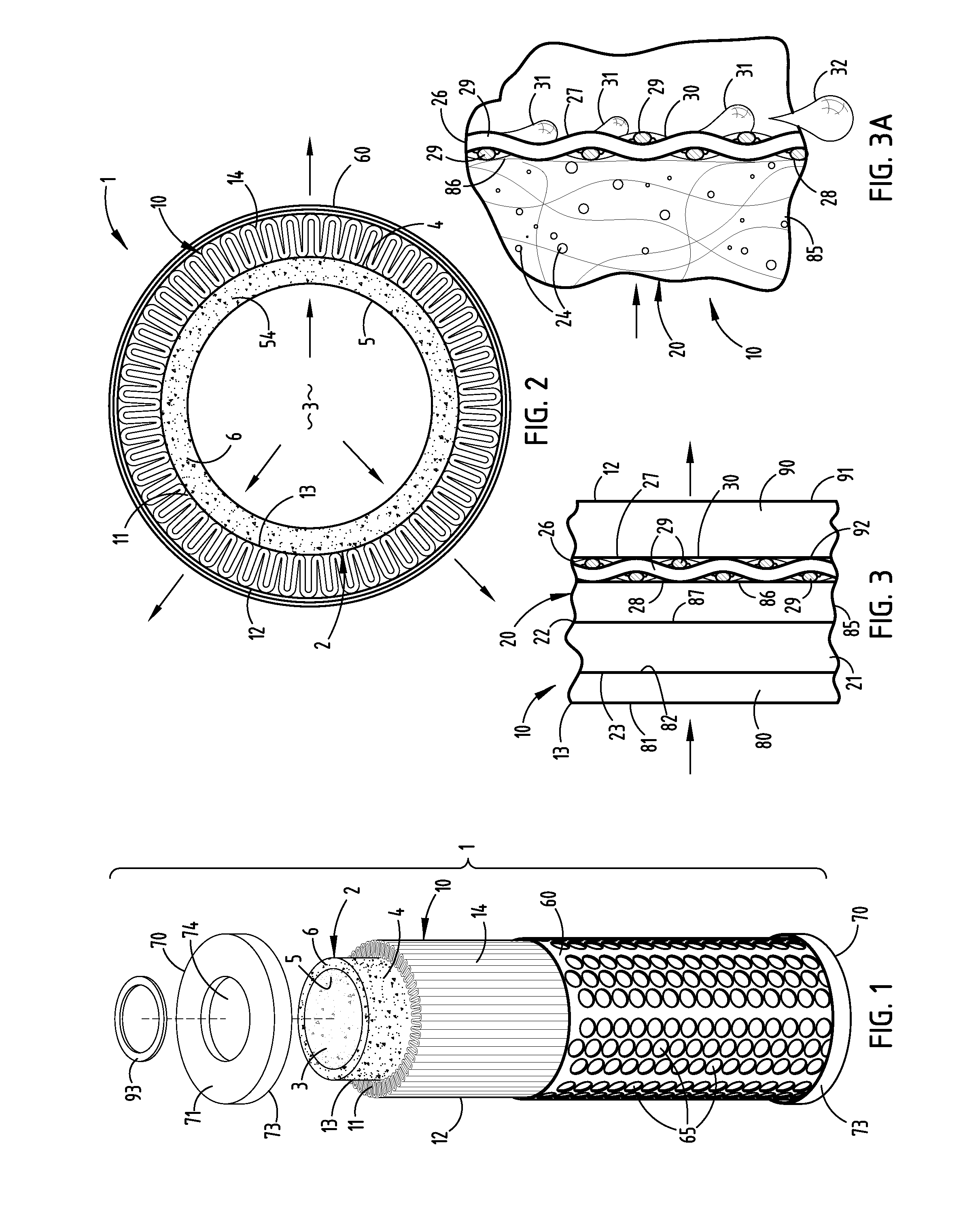
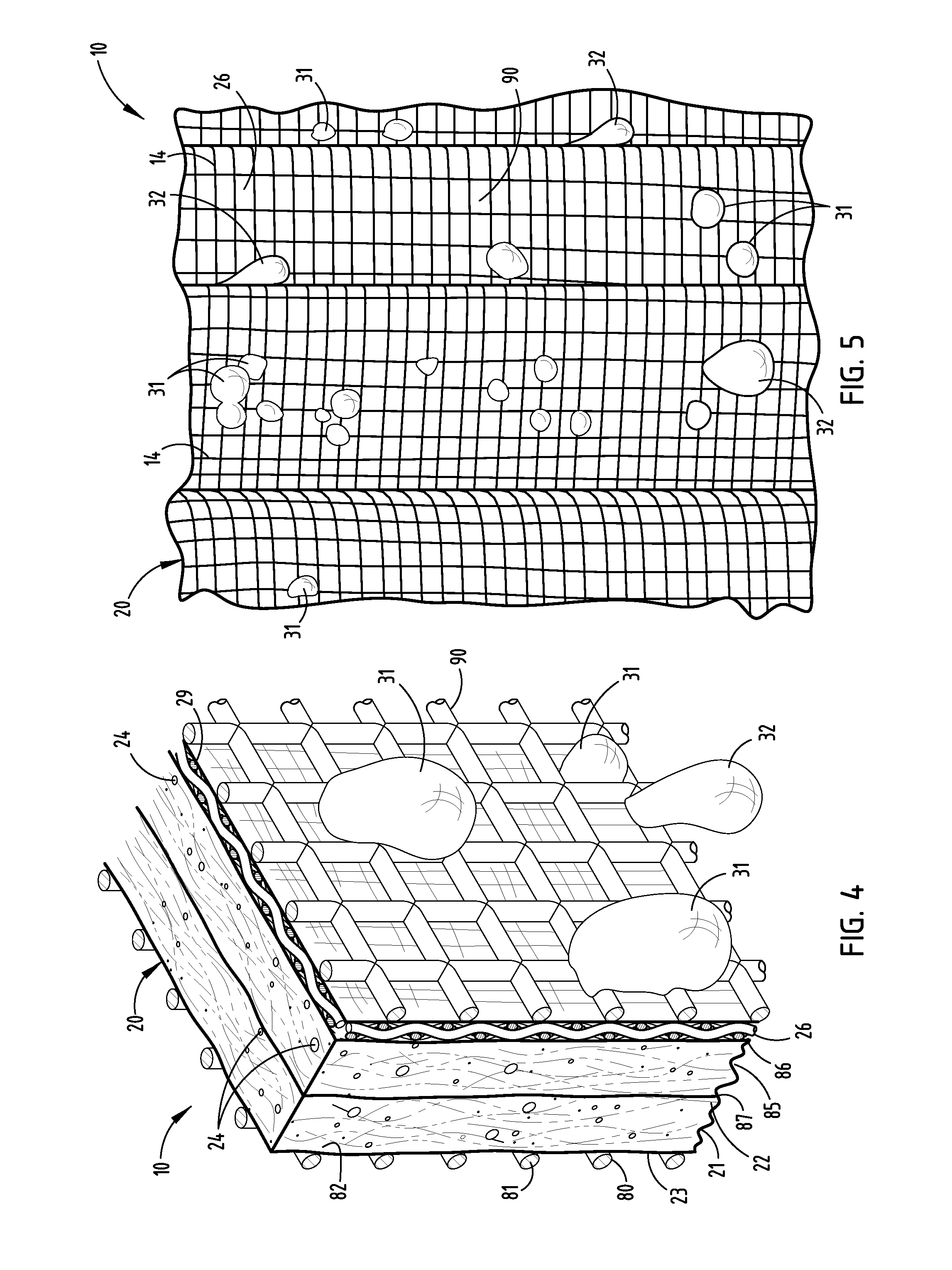
[0111]Additional example two of new pleated coalescence media 20 is made up of two types of fibrous filter media tightly stacked together. One type, at the flow upstream side, is a stack of four layers of media 21, which is non-woven micro fiberglass filter media with a mean flow pore size of 6.5 microns and a water repellency of 5.0 inches of Water Gauge. The other type, at the flow downstream side, is a pile of two layers of media 26, which is precisely woven hydrophilic monofilament mesh with an opening of 18.0 microns and a thread diameter of 31.0 microns. Furthermore, the above six layers of fibrous filter media are retained between two layers of steel mesh screen 90 with a wire diameter of 0.10 inches and a mesh size of 10.0×12.0 per square inch to remain their contact between any two neighboring filter media layers even under hydrodynamic interactions due to through fuel-water blend flow. Finally, all eight layers of both fibrous filter media and steel mes...

example 3

Additional Example 3

[0112]Additional example three of new pleated coalescer media 20 is made up of two types of fibrous filter media tightly stacked together. One type, at the flow upstream side, is a stack of three layers of non-woven fibrous filter media with two different media structures. More specifically, the first non-woven media layer is made of media 107, which is a laminated synthetic filter paper with Frazier air flow of 11.0 CFM / SF @ P ½″ H2O and DOP smoke penetration of 6.0% @ 32 liters / min., and the following two non-woven media layers are made up of media 108, which is non-woven micro fiberglass filter media with an air permeability of 0.26 inches of water gauge and an ASHRAE efficiency (52.1) of 80.0-85.0%. The other type, at the flow downstream side, is one layer of media 26, which is precisely woven hydrophilic monofilament mesh with an opening of 18.0 microns and a thread diameter of 31.0 microns. Furthermore, to remain their contact between any two neighboring fi...


PUM

PropertyMeasurementUnit
Lengthaaaaaaaaaa
Pore sizeaaaaaaaaaa
Angleaaaaaaaaaa

Abstract

A filter system for removing contaminants from oil based industrial liquids and the like includes a support tube with a permeable sidewall through which the industrial liquid flows in an inside out direction. A multilayer coalescence media surrounds the support tube, and includes at least one layer of a non-woven fibrous material that is partially wettable by the dispersed water in the industrial liquid, and commences coalescence of the same to form small primary water droplets, and at least one sheet of a precisely woven monofilament fabric stacked on the downstream side of the non-woven material. The woven fabric is substantially wettable by the dispersed water, and has a fixed open mesh with uniformly sized and spaced apart pore openings which continue to coalesce the primary water droplets into large water drops which fall from the filter for collection along the bottom of the apparatus.

Description

CROSS REFERENCE TO RELATED APPLICATION[0001]This application is a Continuation-In-Part of U.S. patent application Ser. No. 12 / 765,283, filed Apr. 22, 2010, and entitled “COALESCER ELEMENT,” the entire disclosure of which is incorporated herein by reference.BACKGROUND OF THE INVENTION[0002]The present invention relates to filtration systems for removing contaminants from industrial fluids and the like, and in particular to a liquid coalescer media and method.[0003]Filtration systems for industrial fluids are generally well known in the art. For example, contaminants, including solid particles and dispersed contaminant liquid water particles, must be removed from oil based industrial liquids, such as petrochemicals in the nature of gasoline, diesel fuel, jet fuel, gear oil, hydraulic fluid, lubricating oils, etc., organic and / or vegetable oils, bio-fuels, petrodiesel-biodiesel fuel blends, etc., as well as synthetic based lubricants and the like, to ensure proper long term operation a...

Claims


Application Information

Patent Timeline
IPC IPC(8): B01D17/04F16N39/06
CPCF16N39/06B01D17/045B01D36/003B01D29/232B01D29/58C10G31/09C10G33/06C10G53/02B01D2201/0407B01D2239/0421B01D2239/0613B01D2239/0618
Inventor CHEN, RUIJUN
Owner KAYDON CUSTOM FILTRATION CORP
Why Eureka
Try Eureka