Periodicity disturbance suppression device and periodicity disturbance suppression method

a suppression device and periodicity technology, applied in adaptive control, computer control, instruments, etc., can solve the problems of complex production of cogging torque ripple and resistance torque ripple, complex resonance of machines, and vibration, so as to shorten the time needed for learning, increase the robustness against identification model errors, and stabilize the suppression control

Inactive Publication Date: 2014-02-06
MEIDENSHA ELECTRIC MFG CO LTD
View PDF1 Cites 14 Cited by
  • Summary
  • Abstract
  • Description
  • Claims
  • Application Information

AI Technical Summary

Benefits of technology

[0078](1) According to the invention of Claims 1 to 7, an error of a system identification model used for a periodicity disturbance observer can be suitably corrected, and thus, robustness against the errors of the identification model can be increased.
[0079](2) According to the invention of Claim 4, learning (memorization) of a correction value to an error of an identification model of a given frequency is possible, and thus, a learning time until completion of the correction during repeated operation with the identical frequency can be shortened or no learning may be needed.
[0080](3) According to the invention of Claim 5, even when the system identification contains an error, a suppression control can be established by the model correction function and at the same time updat

Problems solved by technology

In case of for example an electric motor as the controlled object that produces the periodicity disturbance, a pulsation called as torque ripple is produced, which causes various problems, such as vibration, noises, poor riding comfort, resonance of machines etc.
Particularly, in widely used magnet embedded type synchronous motors (which will be called PM motor hereinafter), cogging torque ripple and reluctance torque ripple are complicatedly produced.
Although these feedback methods can handle a ripple characteristi

Method used


Image

  • Periodicity disturbance suppression device and periodicity disturbance suppression method
  • Periodicity disturbance suppression device and periodicity disturbance suppression method
  • Periodicity disturbance suppression device and periodicity disturbance suppression method

Examples


first embodiment

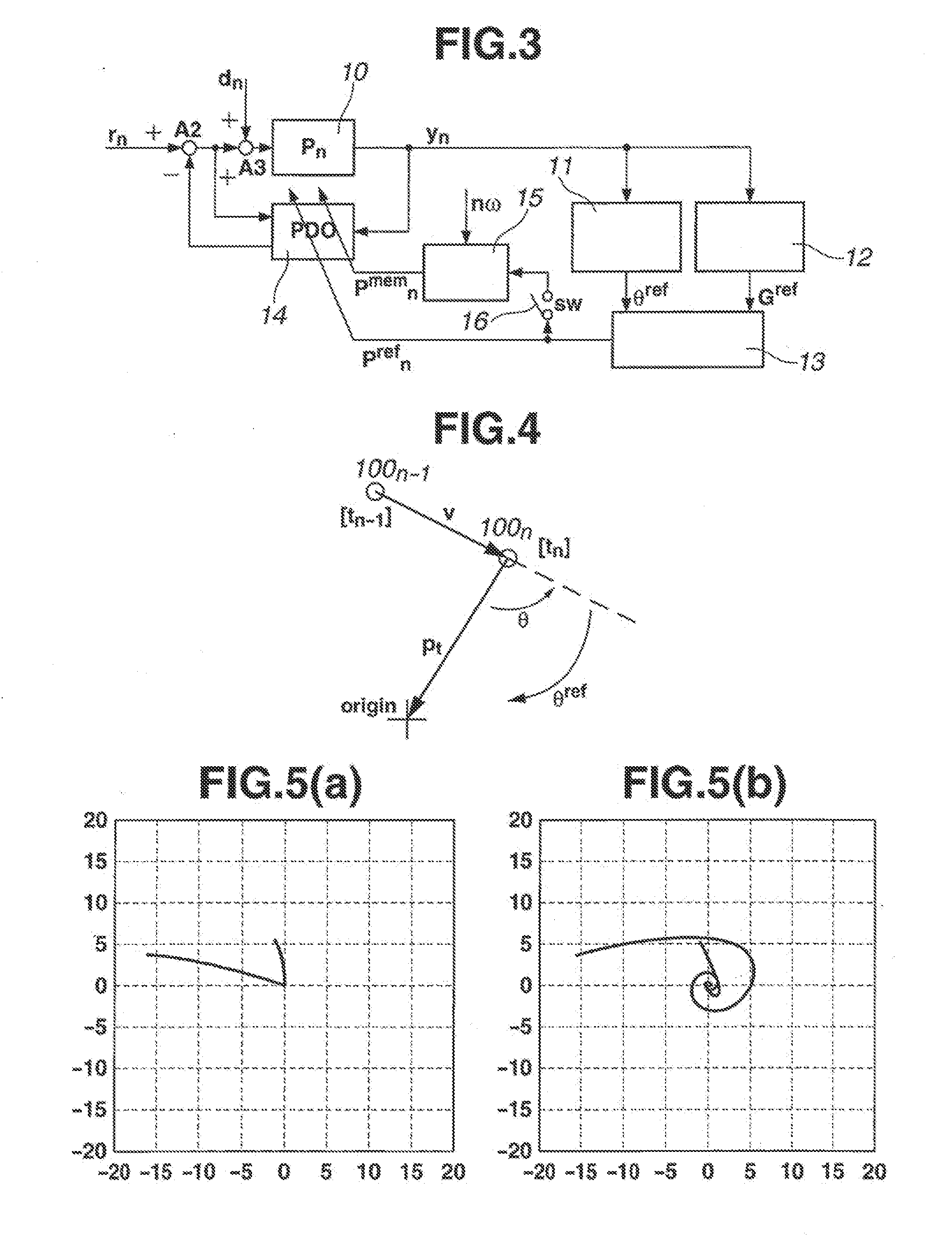
[0106]First, as an output that is to be controlled, attention will be paid to a trajectory of each frequency component of, for example, a torque ripple drawn on a complex vector plane that shows on the real axis n-order torque pulsation extracted component (cosine coefficient) TAn and on the imaginary axis n-order torque pulsation extracted component (sine coefficient) TBn.

[0107]FIG. 4 is a diagram showing a complex vector plane trajectory. Denoted by 100n shows a position (viz., detected present position) that appears when the time elapses by a time [t=tn] from starting of the suppression, and denoted by 100n−1 shows a position (viz., position detected before one period) that appears when the time elapses by a time [t=tn−1] from starting of the suppression.

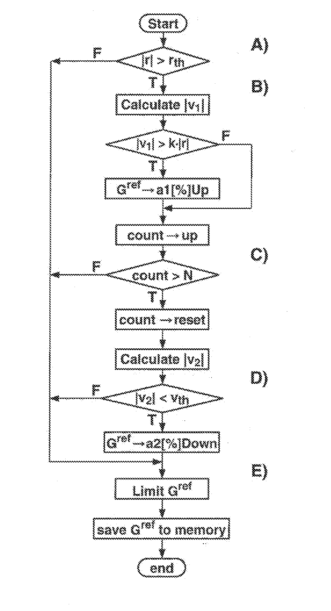
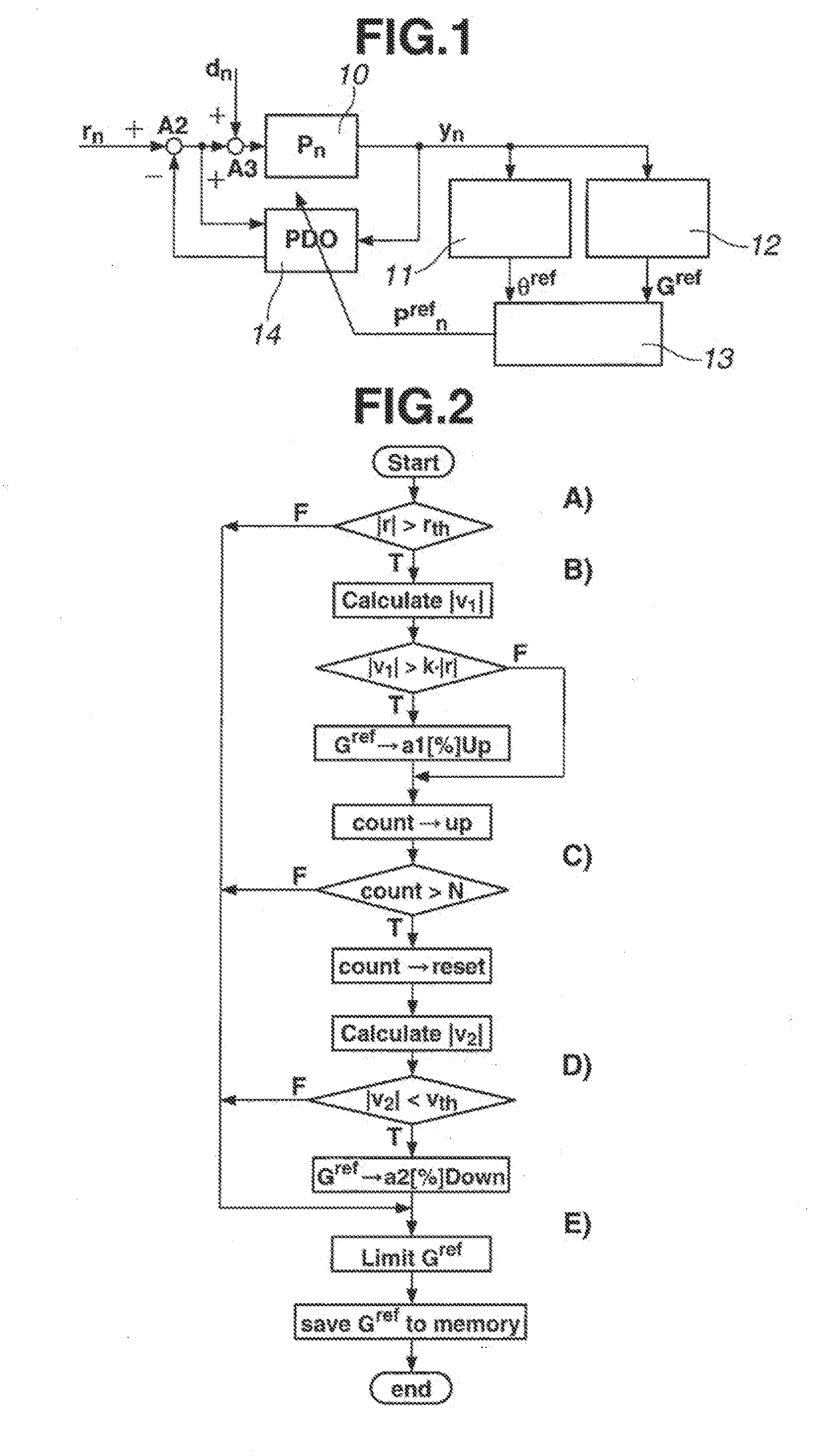
[0108]If the system identification model has no error to a real value, the vector trajectory extends from the control start point to an origin where, as is seen from for example FIG. 5(a) that shows a vector plane trajectory, the...

second embodiment

[0130]In the above-mentioned first embodiment, there is provided a means that suitably corrects, in a given frequency, a system identification model of the periodicity disturbance observer portion. While, in the second embodiment, there is provided a learning (memory) function by providing a memory that is used for memorizing the finally derived corrected value Pnref.

[0131]FIG. 3 shows a block diagram of an identification model correction portion that has the learning function. Denoted by 15 is a memory that inputs through a switch 16 an output Pnref of a rotation vector calculation portion 13 and at the same time inputs an angular velocity nω of PM motor. It is to be noted that the memory 15 and the switch 16 constitute a learning function portion.

[0132]The switch 16 effects ON / OFF operation at such a timing that the finally corrected rotation vector Pnref is received and stored in the memory 15, and the storing timing for the rotation vector is a timing or time when the periodicit...

third embodiment

[0138]For learning a correction amount of the identification model of FIG. 3, the correction amount is stored in a memory (learning function portion). The learning operation is carried out throughout all range for which the device works or in a given range repeating the learning operation while changing the operation point. However, during such learning operation, a mis-learning tends to occur.

[0139]In the third embodiment, a suppression control is turned ON / OFF in order to suppress the mis-learning that would occur when the operation point is moving.

[0140]FIG. 10 shows a process sequence that is carried out by an identification model correction function portion provided by the above-mentioned learning function portion. At step S1, the operation point is moved, and at step S2, judgment is carried out as to whether the movement has been completed or not. If the movement has been completed, the suppression control is started at step S3. At step S4, judgment is carried out as to whethe...


PUM


Abstract

In a torque ripple suppression control effected by a periodicity disturbance observer, it is necessary to consider plant fluctuation and fluctuation of plant characteristics caused by over time usage. Thus, improvement for robustness to an identification model error has been required. For fulfilling this requirement, there is provided a system that includes a phase correction amount calculation portion 11 that derives a phase correction amount by calculating a phase of a vector trajectory drawn by a frequency component of the periodicity disturbance, a gain correction amount calculation portion 12 that derives a gain correction amount by calculating a progress speed of the vector trajectory drawn by the frequency component of the periodicity disturbance and comparing the calculated progress speed with a threshold value and a rotation vector calculation portion 13 that derives a system identification model correction value by multiplying the phase correction amount by the gain correction amount and corrects the system identification model of a periodicity disturbance observer portion 14 based on the system identification model correction value.

Description

TECHNICAL FIELD[0001]The present invention relates to a periodicity disturbance suppression device and a suppression method for suppressing a periodicity disturbance produced by a controlled object.BACKGROUND ART[0002]When a control device with a learning function and a motor control device are in operation, a controlled object sometimes produces a periodicity disturbance.[0003]In case of for example an electric motor as the controlled object that produces the periodicity disturbance, a pulsation called as torque ripple is produced, which causes various problems, such as vibration, noises, poor riding comfort, resonance of machines etc. Particularly, in widely used magnet embedded type synchronous motors (which will be called PM motor hereinafter), cogging torque ripple and reluctance torque ripple are complicatedly produced. For suppressing the production, various methods for suppressing the torque ripple by electrically applying compensation signals to a controlled object to cance...

Claims


Application Information

Patent Timeline
IPC IPC(8): G05D19/02
CPCG05D19/02G05B13/042G05B13/02G05B13/04
Inventor YAMAGUCHI, TAKASHITADANO, YUGOOI, KAZUNOBU
Owner MEIDENSHA ELECTRIC MFG CO LTD
Why Eureka
Try Eureka