
Plasma processing apparatus and diagnosis method thereof

a technology for processing apparatuses and plasma, which is applied in the direction of liquid/fluent solid measurement, process and machine control, instruments, etc., can solve the problems of increasing the size of the apparatus, not taking into account the cost and layout space, and requiring a larger space, so as to achieve small flow rate and low cost

Active Publication Date: 2014-02-13
HITACHI HIGH-TECH CORP
View PDF12 Cites 59 Cited by
  • Summary
  • Abstract
  • Description
  • Claims
  • Application Information

AI Technical Summary

Benefits of technology

The present invention is about providing a plasma processing apparatus and its diagnosis method that can diagnose the operation of a flow-rate controller with high accuracy and at low cost. The diagnosis method involves using existing supply lines for N2 purge and process gases as well as their flow-rate controllers, without using a dedicated mass-flow-rate controller. This makes it easy and affordable to diagnose the flow-rate controller for small flow rates.

Problems solved by technology

However, it does not take into account the cost and layout space.
Thus, there is a problem of an increase in the size of the apparatus as the wafer diameter increases, and requiring a larger space for the gas supply system equipment.

Method used


Image

  • Plasma processing apparatus and diagnosis method thereof
  • Plasma processing apparatus and diagnosis method thereof
  • Plasma processing apparatus and diagnosis method thereof

Examples


embodiment

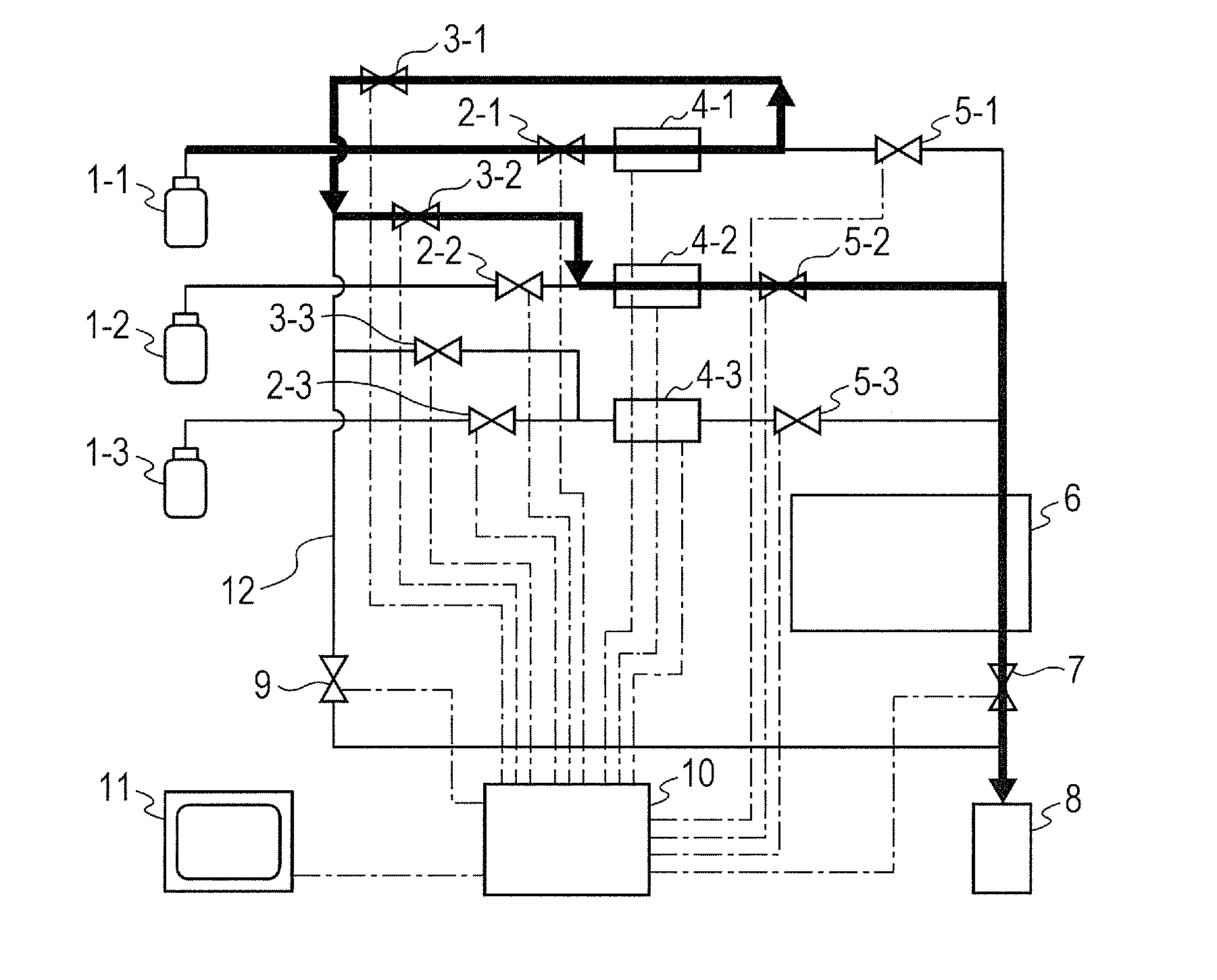
[0024]An embodiment of the present invention will be described with reference to FIGS. 1 to 9. A plasma processing apparatus according to the embodiment is s plasma etching apparatus for performing an etching process of a substrate sample such as a semiconductor wafer placed in a process chamber that is placed in a vacuum vessel, using a plasma formed from a process gas that is supplied to the process chamber and excited by the electric filed or magnetic field introduced into the process chamber.

[0025]FIG. 1 is a schematic block diagram showing the configuration of the plasma processing apparatus according to the embodiment of the present invention. FIG. 1 schematically shows the connection of supply lines including pipes for supplying purge and process gases, to the process chamber within the vacuum vessel and to the exhaust system including a vacuum pump for exhausting the process chamber in the plasma processing apparatus according to the embodiment of the present invention.

[0026...


PUM

PropertyMeasurementUnit
Flow rateaaaaaaaaaa

Abstract

A plasma processing apparatus includes at least three gas supply lines connected to a process chamber in parallel to allow a gas to flow therethrough, and at least three flow-rate controllers provided on the gas supply lines to detect the flow rate of the gas flowing through each of the flow-rate controllers to control the flow rate to a set value and a diagnosis method. The apparatus has a function of splitting and supplying a gas controlled to a predetermined flow rate by the third flow-rate controller, to a first flow-rate controller for the smallest detectable range of the three flow-rate controllers and to a second flow-rate controller, in order to test the operation of the control of the flow rate of the first flow-rate controller, based on the value obtained from the flow rate of the gas flowing through the second flow-rate controller and the predetermined flow rate.

Description

CLAIM OF PRIORITY[0001]The present application claims priority from Japanese Patent Application JP2012-174522 filed on Aug. 7, 2012, the content of which is hereby incorporated by reference into this application.BACKGROUND OF THE INVENTION[0002]1. Field of the Invention[0003]The present invention relates to a plasma processing apparatus for processing a substrate sample such as a semiconductor wafer placed in a process chamber within a vacuum vessel by a plasma formed in the process chamber. The present invention also relates to a diagnosis method of a plasma processing apparatus for diagnosing the operation of a flow-rate controller that controls the flow rate of a process gas supplied to the process chamber of the plasma processing apparatus.[0004]2. Description of the Related Art[0005]A plasma processing apparatus has been widely used for forming the structure of a device circuit by applying a desired process to a substrate sample such as a silicon semiconductor wafer or an LCD s...

Claims


Application Information

Patent Timeline
IPC IPC(8): G01F7/00B05C11/00
CPCC23C16/45561C23C16/52G05D7/0658
Inventor NAGATANI, MASAHIROOGAWA, YOSHIFUMI
Owner HITACHI HIGH-TECH CORP
Features
  • Generate Ideas
  • Intellectual Property
  • Life Sciences
  • Materials
  • Tech Scout
  • Unparalleled Data Quality
  • Higher Quality Content
  • 60% Fewer Hallucinations
Learn More