Stimulated raman scattering detection apparatus

a detection apparatus and raman scattering technology, which is applied in the direction of optical radiation measurement, instruments, spectrometry/spectrophotometry/monochromators, etc., can solve the problems of deteriorating the signal-to-noise ratio of the laser source, requiring frequent extensive maintenance, and generating a large intensity noise component of the laser output of the stable small laser such as the fiber laser, so as to reduce the intensity noise component and improve the s/n ratio of the detection ligh

Active Publication Date: 2014-02-13
CANON KK
View PDF4 Cites 10 Cited by
  • Summary
  • Abstract
  • Description
  • Claims
  • Application Information

AI Technical Summary

Benefits of technology

[0006]The present invention provides an SRS detection apparatus capable of reducing the intensity noise component included in the light pulses to be focused onto the sample to improve the S/N ratio of the detection light. The present invention provides as an aspect thereof a stimulated Raman scattering detection apparatus including a first light pulse generator configured to generate first light pulses with a first pulse period, a second light pulse generator configured to generate second light pulses with a second pulse period shorter than the first pulse period, the second light pulse having a light frequency different from that of the first light pulse, an optical system configured to combine the first and second light pulses and configured to focus the combined first and second light pulses onto a sample, and a detector configured to detect the second light pulses intensity-mo

Problems solved by technology

However, the SRS detection apparatus requires a light source generating extremely low noise close to a shot noise limit, which provides a restriction to a laser light source.
Thus, the SRS detection apparatus needs a light source using a solid laser or an optical parametric oscillator which requires frequent extensive maintenance.
On the other hand, a stabl

Method used


Image

  • Stimulated raman scattering detection apparatus
  • Stimulated raman scattering detection apparatus
  • Stimulated raman scattering detection apparatus

Examples


example 1

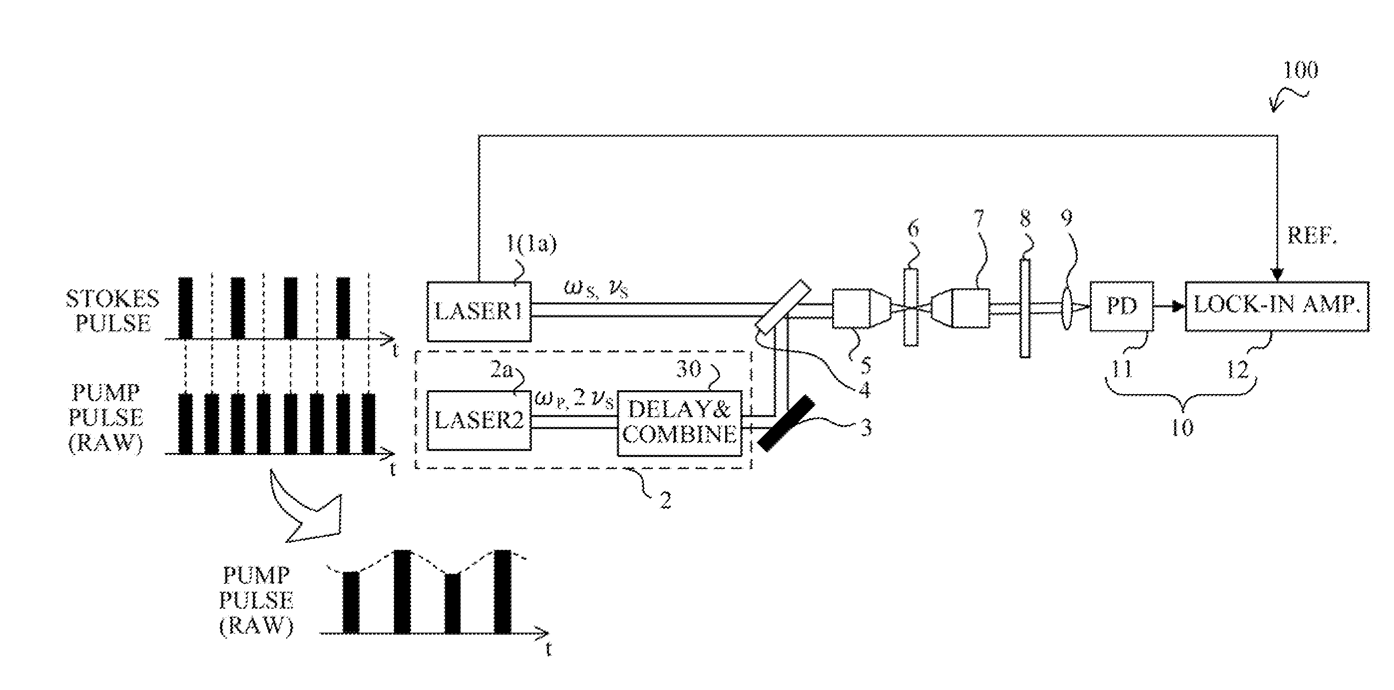
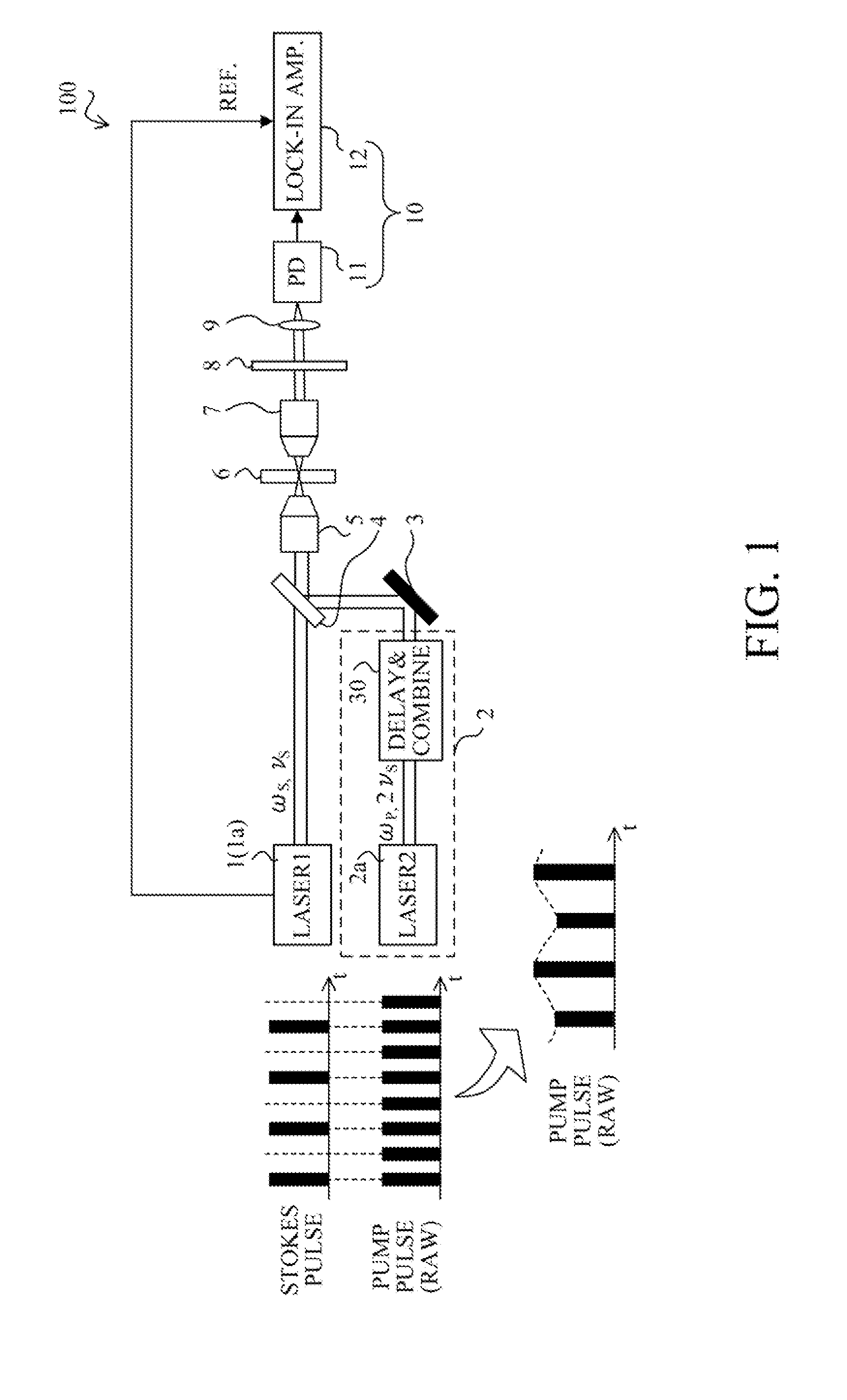
[0017]FIG. 1 schematically shows a configuration of a stimulated Raman scattering (SRS) detection apparatus that is a first embodiment (Embodiment 1) of the present invention. The SRS detection apparatus 100 can be used as apparatuses such as a microscope and an endoscope for observation, measurement, diagnosis and other usages.

[0018]The SRS detection apparatus 100 of this embodiment includes a first light pulse generator 1 that generates a first light pulse train to be used as Stokes light, and a second light pulse generator 2 that generates a second light pulse train to be used as pump light. Moreover, the detection apparatus 100 includes an optical system by a mirror 3, a half mirror 4, a first objective lens 5, a second objective lens 7, a color filter 8 and a collective lens 9. Furthermore, the detection apparatus 100 includes a detector 10 constituted by a photodiode 11 that is a light-receiving element and a lock-in amplifier 12 that is an electronic circuit synchronously det...

example 2

[0057]FIG. 6 shows a detailed configuration of a delaying and combining part 30 in an SRS detection apparatus that is a second embodiment (Embodiment 2) of the present invention.

[0058]A raw light pulse L0 emitted from a second light source 2a is reflected by a first mirror M1 provided in the delaying and combining part 30 and then transmitted through a half wave plate WP to enter a polarization beam splitter PBS. The polarization beam splitter PBS reflects an S-polarized light pulse L2 that is one light pulse of the entering raw light pulse L0 and transmits the a P-polarized light pulse L1 that is the other light pulse of the raw light pulse L0. Thereby, the raw light pulse L0 is divided into the P- and S-polarized light pulses L1 and L2 that are two light pulses. Adjusting an azimuth of an optic axis of the half wave plate WP makes it possible to equalize intensities of the P- and S-polarized light pulses L1 and L2 to each other.

[0059]The S-polarized light pulse L2 reflected by the...

example 3

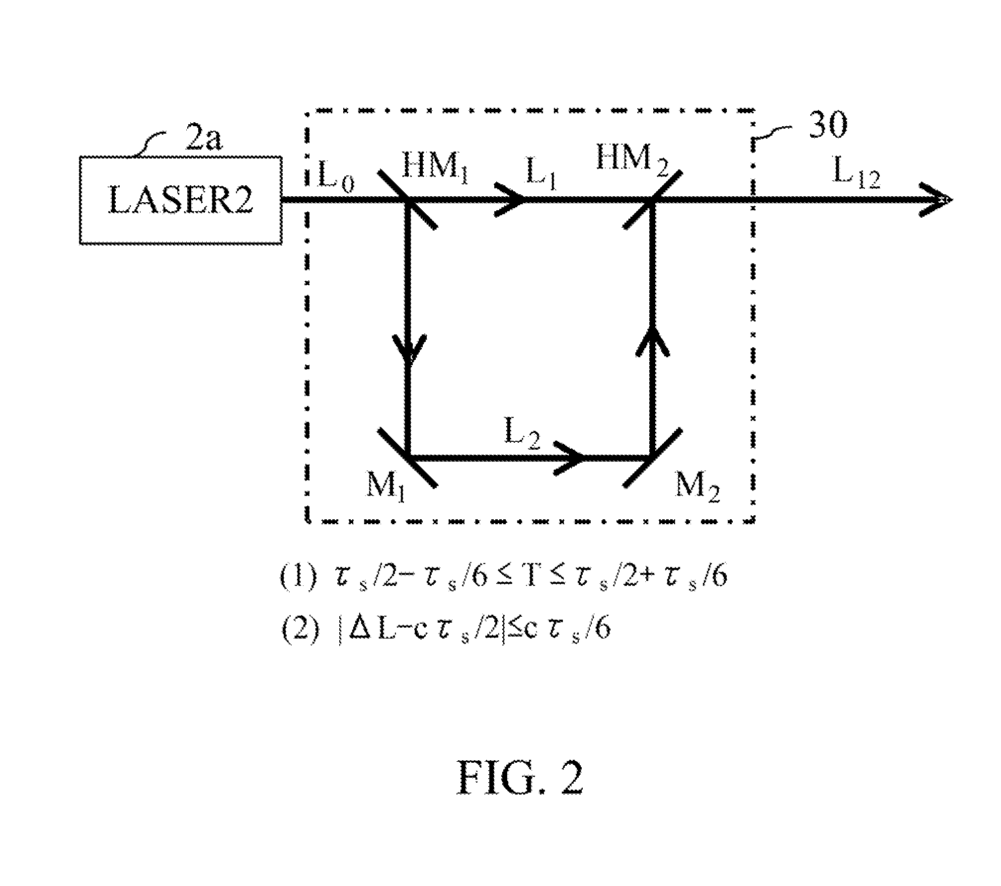
[0065]FIG. 7 shows a detailed configuration of a delaying and combining part 30 in an SRS detection apparatus that is a third embodiment (Embodiment 3) of the present invention. This embodiment is a modified example, and constituent elements of the delaying and combining part 30 are same as those in Embodiment 1.

[0066]Although description was made of a possibility of the interference between the two light pulses to be combined when the delay time T is set to τS / 2 in Embodiment 2, this embodiment will describe a method to avoid that possibility without using polarized light as Embodiment 2. Specifically, this embodiment sets the delay time T within the range shown by the expression (1) in Embodiment 1 and within a range shown by the following expression (3) where p represents a pulse width of the second light pulse:

|T−(τS / 2)|≧2p  (3)

[0067]On the basis of the expression (3), an optical path length difference ΔL of the delaying optical path where the light pulse L2 passes from the opti...


PUM


Abstract

The stimulated Raman scattering detection apparatus includes first and second light pulse generators (1, 2) respectively generating first and second light pulses with first and second pulse periods, an optical system combining the first and second light pulses and focusing the combined light pulses onto a sample, and a detector (10) detecting the second light pulses intensity-modulated by stimulated Raman scattering generated by focusing of the combined light pulses onto the sample. The second light pulse generator divides each raw light pulse emitted with the second pulse period into two light pulses, delays one of the two light pulse with respect to the other thereof and combines the one light pulse divided from one raw light pulse and delayed, with the other light pulse divided from another raw light pulse emitted after the one raw light pulse, to generate the second light pulse.

Description

TECHNICAL FIELD[0001]The present invention relates to a stimulated Raman scattering detection apparatus to be used for a microscope, an endoscope and the like performing molecular vibration imaging by utilizing stimulated Raman scattering.BACKGROUND ART[0002]A stimulated Raman scattering (SRS) detection apparatus that is one of detection apparatuses utilizing a Raman scattering principle has been proposed in “Principle confirmation of stimulated Raman scattering microscopy” by Fumihiro Dake et al. and “Label-free biomedical imaging with high sensitivity by stimulated Raman scattering microscopy” by Chiristian W. Freudiger et al. The principle of the SRS detection apparatus is as follows.[0003]When two light pulses whose light frequencies are mutually different are focused onto a sample, a coincidence of a difference between the light frequencies of the two light pulses with a molecular vibration frequency causes a phenomenon of stimulated Raman scattering at a light-focused point, t...

Claims


Application Information

Patent Timeline
IPC IPC(8): G01J3/44
CPCG01J3/4412G01N21/65G01N2021/655H01S3/005H01S3/2391G01J3/433G01J3/44
Inventor OZEKI, YASUYUKIITOH, KAZUYOSHINOSE, KEISUKE
Owner CANON KK
Why Eureka
Try Eureka