Anode for electrowinning and method for electrowinning using same

Inactive Publication Date: 2014-02-27
DOSHISHA CO LTD
View PDF2 Cites 5 Cited by
  • Summary
  • Abstract
  • Description
  • Claims
  • Application Information

AI Technical Summary

Benefits of technology

[0050]The present invention pro

Problems solved by technology

However, the manganese compound or the lead dioxide have a low catalytic activity for the occurrence of oxygen and a lower electrical conductivity, thus inhibiting the reaction for the occurrence of oxygen on the anode.
This will lead to an increase in the potential of the anode, causi

Method used


Image

  • Anode for electrowinning and method for electrowinning using same

Examples


Example

Example 1

[0054]A commercially available titanium plate (5 cm in length, 1 cm in width, 1 mm in thickness) was immersed and etched in a 10% oxalic acid solution at 90° C. for 60 minutes and then washed and dried. Next, prepared was an application liquid which was obtained by adding ruthenium trichloride trihydrate (RuCl3.3H2O) and tantalum pentachloride (TaCl5) to a butanol (n-C4H9OH) solution containing 6 vol % concentrated hydrochloric acid so that the molar ratio between ruthenium and tantalum is 30:70 and the total of ruthenium and tantalum is 50 g / L in terms of metal. This application liquid was applied to the titanium plate dried as mentioned above, dried at 120° C. for 10 minutes, and then thermally decomposed for 20 minutes in an electric furnace that was held at 260° C. This series of application, drying, and thermal decomposition was repeated five times in total in order to prepare an anode for electrowinning according to Example 1, the anode having a catalytic layer formed...

Example

Example 2

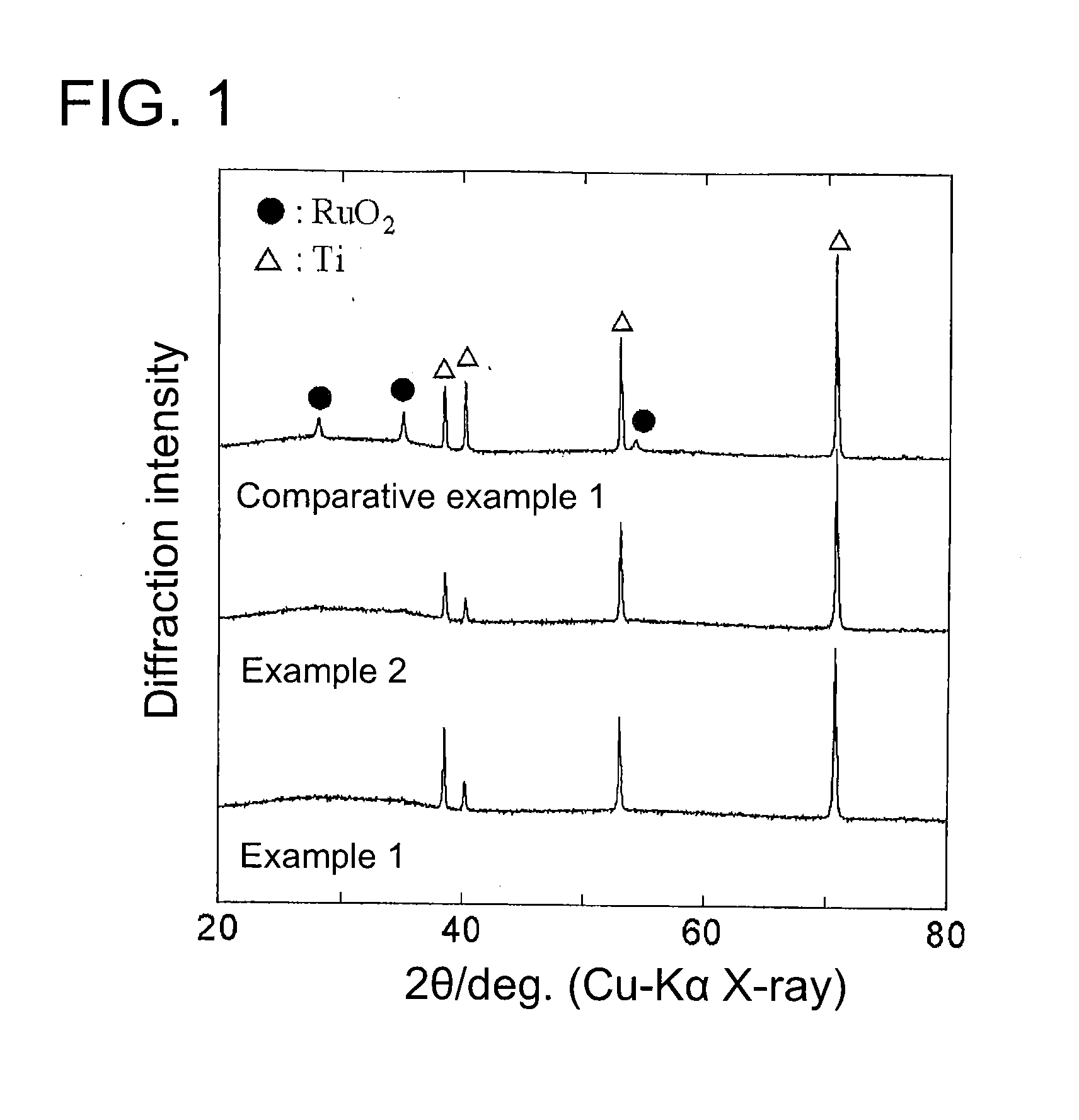
[0057]An anode for electrowinning according to Example 2 was manufactured by the same method as that of Example 1 except that the catalytic layer was formed at a thermal decomposition temperature of not 260° C. but 280° C. An X-ray diffraction analysis of the structure of the anode for electrowinning according to Example 2 shows that as shown in FIG. 1, the diffraction peak equivalent to RuO2 was not observed, and the diffraction peak equivalent to Ta2O5 was not observed, either. Note that the diffraction peak of Ti was observed; however, this was caused by the titanium plate. That is, the anode for electrowinning according to Example 2 had the catalytic layer of amorphous ruthenium oxide and amorphous tantalum oxide formed on the titanium plate.

[0058]Prepared was an electrolytic solution of a 0.80 mol / L of ZnSO4 and 2.0 mol / L of sulfuric acid, and a zinc plate (2 cm×2 cm) was immersed as the cathode in this electrolytic solution. Furthermore, the anode for electrowinning a...

Example

Comparative Example 1

[0059]An anode for electrowinning according to Comparative Example 1 was manufactured by the same method as that of Example 1 except that the catalytic layer was formed at a thermal decomposition temperature of not 260° C. but 360° C. An X-ray diffraction analysis of the structure of the anode for electrowinning according to Comparative Example 1 shows that as shown in FIG. 1, the diffraction peak equivalent to RuO2 was observed, but the diffraction peak equivalent to Ta2O5 was not observed. Note that the diffraction peak of Ti was observed; however, this was caused by the titanium plate. That is, the anode for electrowinning according to Comparative Example 1 had the catalytic layer of crystalline ruthenium oxide and amorphous tantalum oxide formed thereon.

[0060]Prepared was an electrolytic solution of a 0.80 mol / L of ZnSO4 and 2.0 mol / L of sulfuric acid, and a zinc plate (2 cm×2 cm) was immersed as the cathode in this electrolytic solution. Furthermore, the an...


PUM

PropertyMeasurementUnit
Electric potential / voltageaaaaaaaaaa
Electrical conductoraaaaaaaaaa

Abstract

Provided is an anode for electrowinning in a sulfuric acid based electrolytic solution. The anode produces oxygen at a lower potential than a lead electrode, lead alloy electrode, and coated titanium electrode, thereby enabling electrowinning to be performed at a reduced electrolytic voltage and the electric power consumption rate of a desired metal to be reduced. The anode is also available as an anode for electrowinning various types of metals in volume with efficiency. The anode is employed for electrowinning in a sulfuric acid based electrolytic solution and adopted such that a catalyst layer containing amorphous ruthenium oxide and amorphous tantalum oxide is formed on a conductive substrate.

Description

TECHNICAL FIELD[0001]The present invention relates to an anode employed for electrowinning a desired metal by electrolysis and to a method for electrowinning using the same. More particularly, the present invention relates to an anode employed for electrowinning in a sulfuric acid based electrolytic solution with oxygen produced by anode reaction and to a method for electrowinning using the same.BACKGROUND ART[0002]Electrowinning of a metal is performed by submerging and energizing an anode and a cathode in an aqueous solution (hereafter referred to as the electrolytic solution) which contains ions of a metal to be extracted, thereby allowing the metal to be deposited on the cathode. Examples of typical electrowinning may include a method for electrowinning a metal by electrolysis in an electrolytic solution. In this case, to prepare an electrolytic solution, an ore is first crushed which contains any one or more of copper, zinc, nickel, cobalt, lead, platinum family metals (such as...

Claims


Application Information

Patent Timeline
IPC IPC(8): C25C7/02C25C1/16C25C1/08C25C1/12
CPCC25C7/02C25C1/08C25C1/16C25C1/12
Inventor MORIMITSU, MASATSUGU
Owner DOSHISHA CO LTD
Why Eureka
Try Eureka