Fundus imaging apparatus, method of controlling fundus imaging apparatus, and storage medium
- Summary
- Abstract
- Description
- Claims
- Application Information
AI Technical Summary
Benefits of technology
Problems solved by technology
Method used
Image

Examples
first embodiment
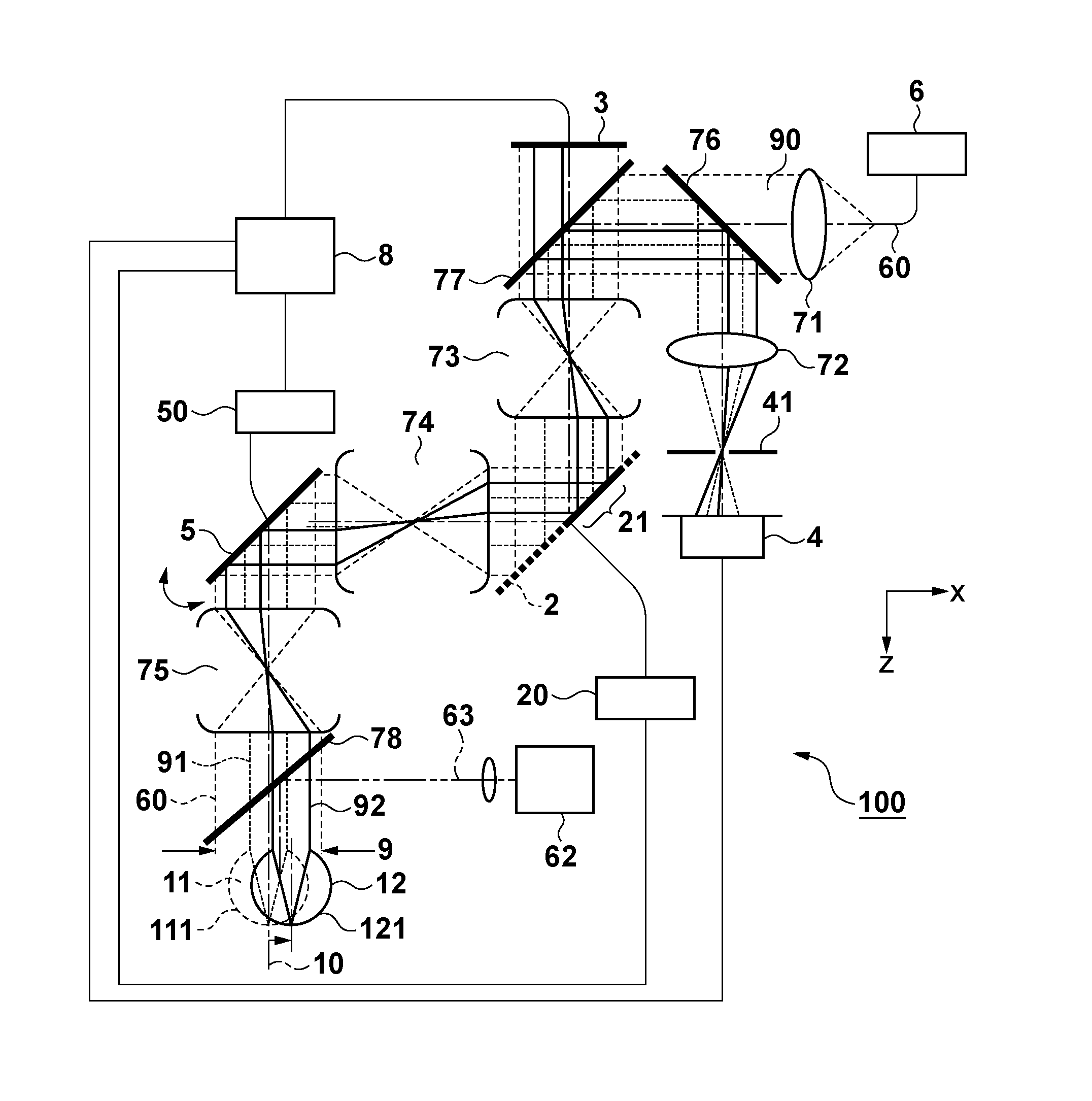
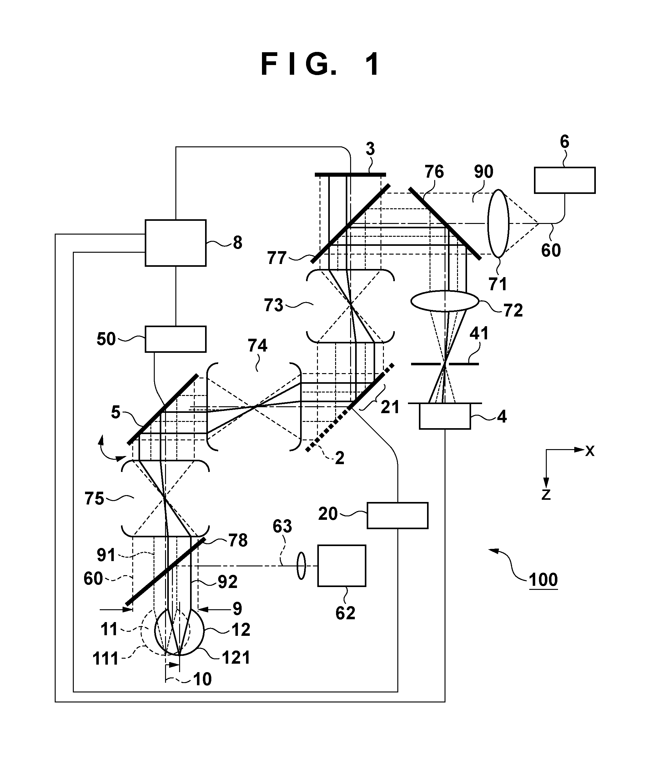
[0032]The arrangement of a scanning laser ophthalmoscope (SLO) according to the first embodiment of the present invention will be described first with reference to FIG. 1. In an SLO 100, first of all, light from an image obtaining laser light source 6 propagates in a single-mode fiber 60 and emerges, as illumination light 90, from a fiber end. A collimator lens 71 converts the emerging illumination light 90 into parallel light (the broken lines indicate the marginal rays of the illumination light 90 and the effective diameter range of the optical system).
[0033]The illumination light 90 which has been converted into parallel light is transmitted through a half mirror 76, reflected by a first dichroic mirror 77, and reflected by an aberration correction device 2 through a first afocal optical system 73. The light then strikes a scanner mirror 5 through a second afocal optical system 74. An eyepiece optical system 75 causes the illumination light 90 reflected by the scanner mirror 5 to...
second embodiment
[0055]An SLO 101 according to the second embodiment of the present invention will be described next with reference to FIG. 7. The basic arrangement of the second embodiment and reference numerals denoting the respective units are the same as those of the first embodiment described with reference to FIG. 1. FIG. 7 shows an x-z plane. The arrangement in FIG. 7 differs from that in FIG. 1 in that the light beam diameter of illumination light 90 is set to the same diameter as the eye to be examined, that is, 6 mm, and a mirror 79 is placed between a collimator lens 71 and a half mirror 76. The illumination light 90 collimated by the collimator lens 71 is reflected by the mirror 79 at an almost right angle and propagates along the optical system after the first half mirror. In addition, the mirror 79 is placed on a mechanism which shifts reflected light from the mirror in the optical axis direction. In this embodiment, the image obtaining illumination light 90 also serves as wavefront de...
third embodiment
[0059]An adaptive optics unit 102 of a fundus imaging apparatus according to the third embodiment will be described with reference to FIG. 8. FIG. 8 shows only a portion indicating the relationship between the eye to be examined and an aberration correction device 2. The same reference numerals denote the same parts as in the first embodiment described with reference to FIG. 1. FIG. 8 shows an x-z plane. This embodiment uses a phase spatial modulator (SLM) using a liquid crystal as the aberration correction device 2. A deformable mirror is designed to change an optical path length by changing the shape of the mirror to change the spatial distance. In contrast to this, the SLM is designed to correct a wavefront by changing the refractive index of the liquid crystal so as to change the optical path length as refractive index x spatial distance. FIG. 8 shows a transmission type SLM. However, it is possible to use a reflection type SLM.
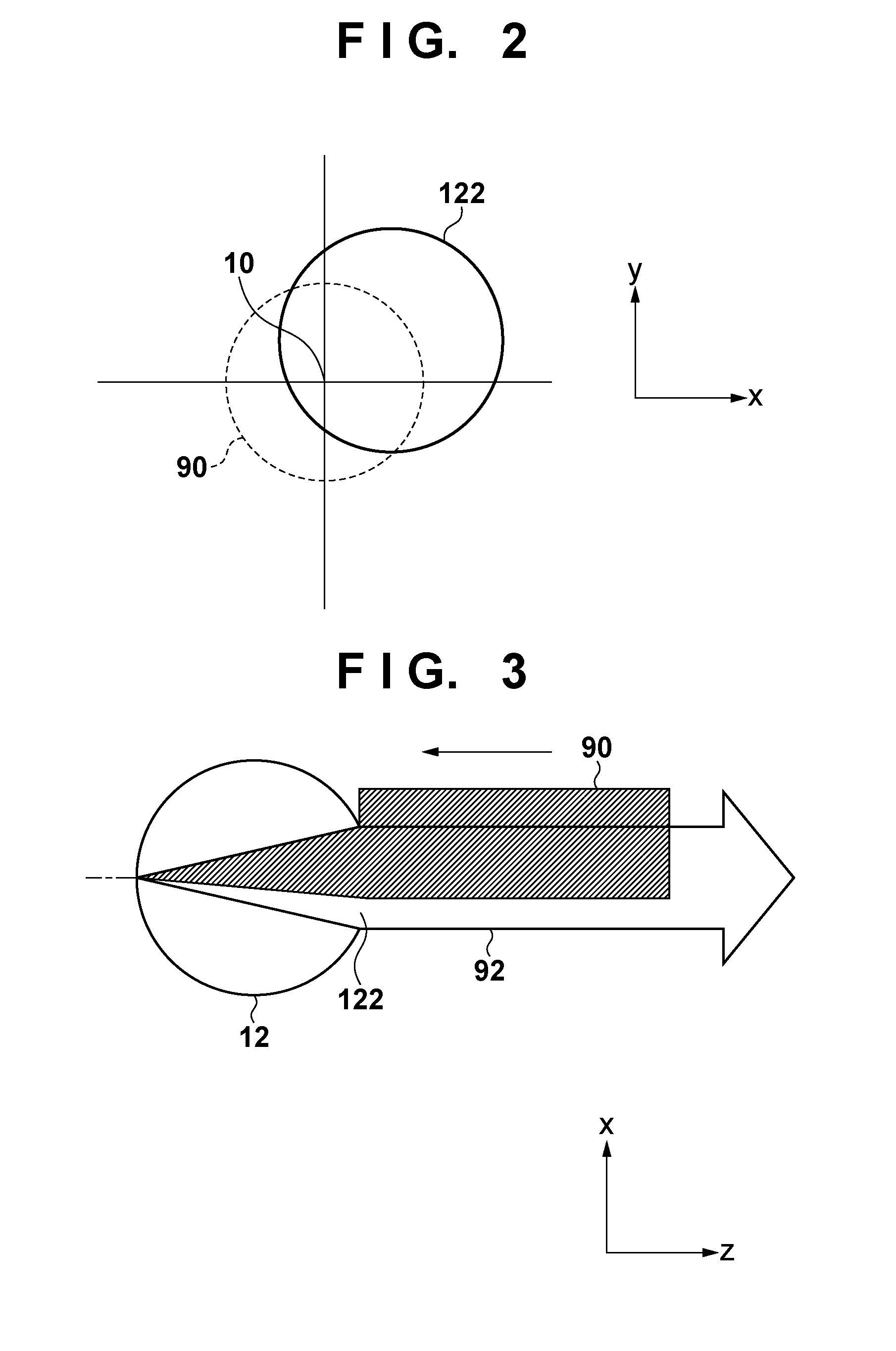
[0060]Referring to FIG. 8, a pupil 122 of an eye 12...
PUM
 Abstract
Description
Claims
Application Information
 - R&D Engineer
- R&D Manager
- IP Professional
- Industry Leading Data Capabilities
- Powerful AI technology
- Patent DNA Extraction
Browse by: Latest US Patents, China's latest patents, Technical Efficacy Thesaurus, Application Domain, Technology Topic.
© 2024 PatSnap. All rights reserved.Legal|Privacy policy|Modern Slavery Act Transparency Statement|Sitemap