
Capacitor discharge pulse drive circuit with fast recovery

Inactive Publication Date: 2014-03-06
BERENDT MARTIN OLE
View PDF5 Cites 23 Cited by
  • Summary
  • Abstract
  • Description
  • Claims
  • Application Information

AI Technical Summary

Benefits of technology

This patent introduces a new technology that solves the issue of slow charging in previous laser systems. It uses a capacitive discharge circuit and a passively self gating switched charge part to significantly reduce the charge time. The patent also mentions the creation of short pulses with a high peak power that can help in suppressing nonlinear scattering and facilitate nonlinear frequency conversion in fiber laser systems.

Problems solved by technology

For higher pulse repetition rates, the same as shorter pulse repetition periods the circuit does not have enough time to fully charge the capacitor.

Method used


Image

  • Capacitor discharge pulse drive circuit with fast recovery
  • Capacitor discharge pulse drive circuit with fast recovery
  • Capacitor discharge pulse drive circuit with fast recovery

Examples


Embodiment Construction

[0033]Further features and advantages of the invention as well as the structure and operation of exemplary embodiments of the invention are described in detail below, with reference to the accompanying FIGS. 3-10, wherein reference numerals have the FIG. number as the leading number.

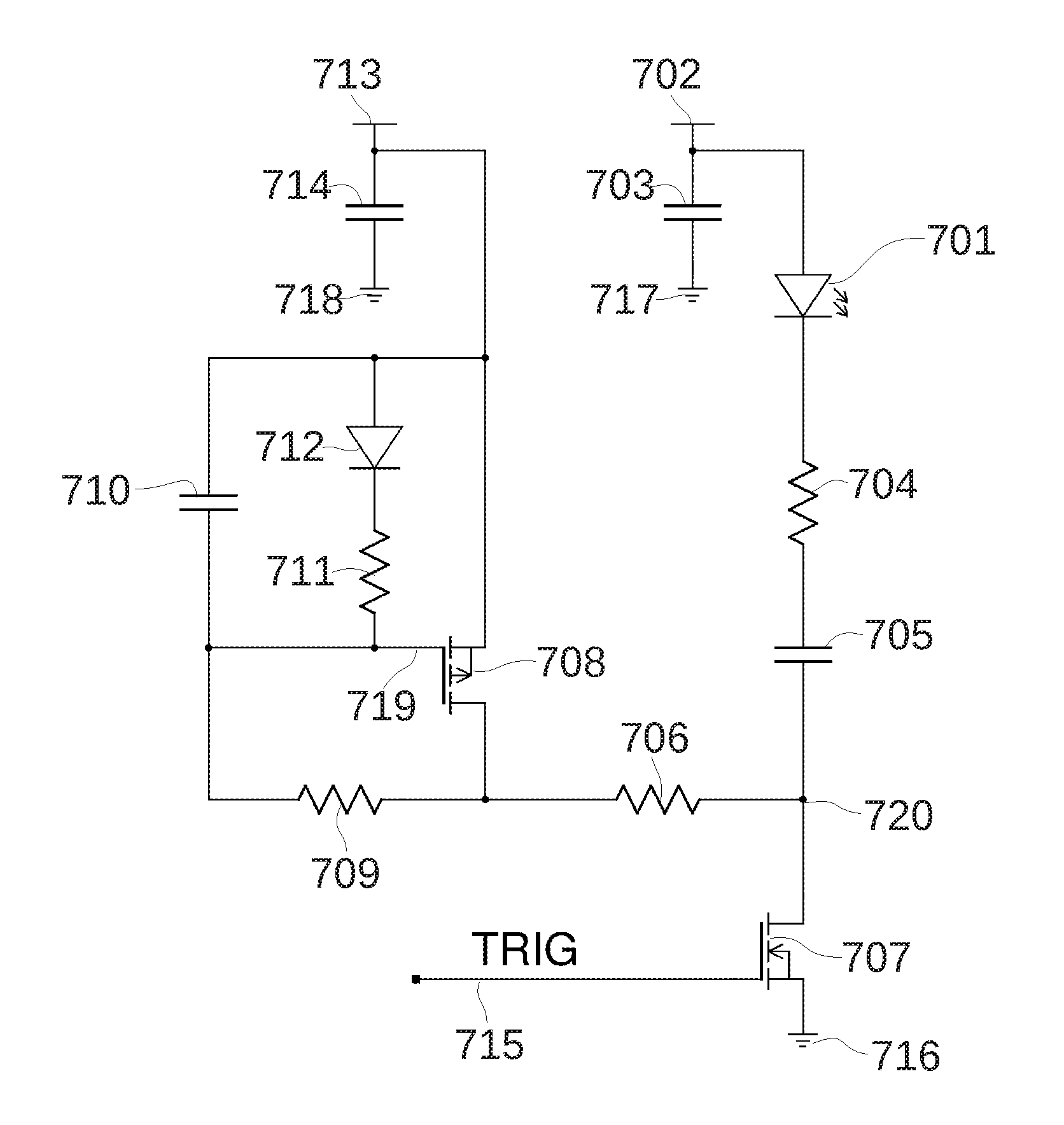
[0034]One exemplary embodiment of the present invention is illustrated in FIG. 7. A capacitive discharge pulse circuit comprises the capacitor 705, pulse forming resistor 704 and the laser diode supply 702, which is buffered to ground 717 by the decoupling capacitor 703. By switching the N-type MOSFET transistor 707 to its ON-state by driving the TRIG signal line 715 high, the falling voltage edge on the capacitor 705 drives a forward current spike through the laser diode load 701. The capacitor recharge circuit of the invention is embodied by the P-channel MOSFET 708 as switching and current limiting element and the delay element formed by the resistors 706 and 709 in combination with the capacitor 710 ...


PUM


Abstract

A circuit apparatus for driving short current pulses through a laser diode is disclosed. The circuit allow fast recovery time, comparable to the pulse duration. This enables high duty cycle pulse trains and bursts. The fast recovery is achieved by a passively self gated charging of the pulse circuit.

Description

BACKGROUND OF THE INVENTION[0001]1. Field of the Invention[0002]The present invention relates generally to electrical pulse generation, and more particularly optical pulse generation by driving current pulses through a laser diode.[0003]One application is within seeding of high power amplifiers, e.g. fiber optical amplifiers. This find application in master oscillator power amplifier laser systems.[0004]The advantage of the disclosed pulse drive technique is its fast recovery time which among other things enable high duty cycle pulse bursts.[0005]2. Description of Related Art[0006]A widely used method for generating short i.e. less than a few tens of ns (1E-9 seconds) current pulse through a load, often a laser diode rely on fast discharge of a capacitor coupled to the laser diode. Using a small capacitance value on the order of 100 pF (1E-10 Farads) gives a pulse spike with good immunity to impedance mismatch. This is often used for driving large junction laser diodes to peak power...

Claims


Application Information

Patent Timeline
IPC IPC(8): H01S5/042H01S3/067H03K3/57
CPCH01S5/0428H01S3/067H03K3/57
Inventor BERENDT, MARTIN OLE
Owner BERENDT MARTIN OLE
Learn More