Automated superalloy laser cladding with 3D imaging weld path control

a superalloy and laser cladding technology, applied in the direction of turbines, manufacturing tools, solventing apparatus, etc., can solve the problems of difficult subsequent structural welding, difficult to repair nickel and cobalt based superalloy materials used to manufacture turbine components, and blades that are susceptible to solidification cracking (aka liquation cracking)

Inactive Publication Date: 2014-03-13
SIEMENS ENERGY INC
View PDF2 Cites 28 Cited by
  • Summary
  • Abstract
  • Description
  • Claims
  • Application Information

AI Technical Summary

Benefits of technology

[0019]An additional object is to create turbine component laser cladding systems or methods that in real time or sequentially: acquire dimensional data, compare acquired dimensional data with specification data, determine a welding path and welding processes for building up the component surface in in conformity with the determined welding pattern, and perform the

Problems solved by technology

Repair of nickel and cobalt based superalloy material that is used to manufacture turbine components, such as turbine blades, is challenging, due to the metallurgic properties of the finished blade material.
The finished turbine blade alloys are typically strengthened during post casting heat treatments, which render them difficult to perform subsequent structural welding.
When a blade constructed of such a superalloy material is welded with filler metal of the same or similar alloy, the blade is susceptible to solidification (aka liquation) cracking within and proximate to the weld, and/or strain age (aka reheat) cracking during subsequent heat treatment processes intended to restore the superalloy original strength and other material properties comparable to a new component.
Creating arrays of laser-clad deposits often results in microcracks and defects in the deposited material and underlying substrate in the heat affected zone material.
Some defects are related to lack of fusion (LoF) that is common when there is insufficient localized laser optical energy heat input.
Voids or cracks remaining a

Method used


Image

  • Automated superalloy laser cladding with 3D imaging weld path control
  • Automated superalloy laser cladding with 3D imaging weld path control
  • Automated superalloy laser cladding with 3D imaging weld path control

Examples


Embodiment Construction

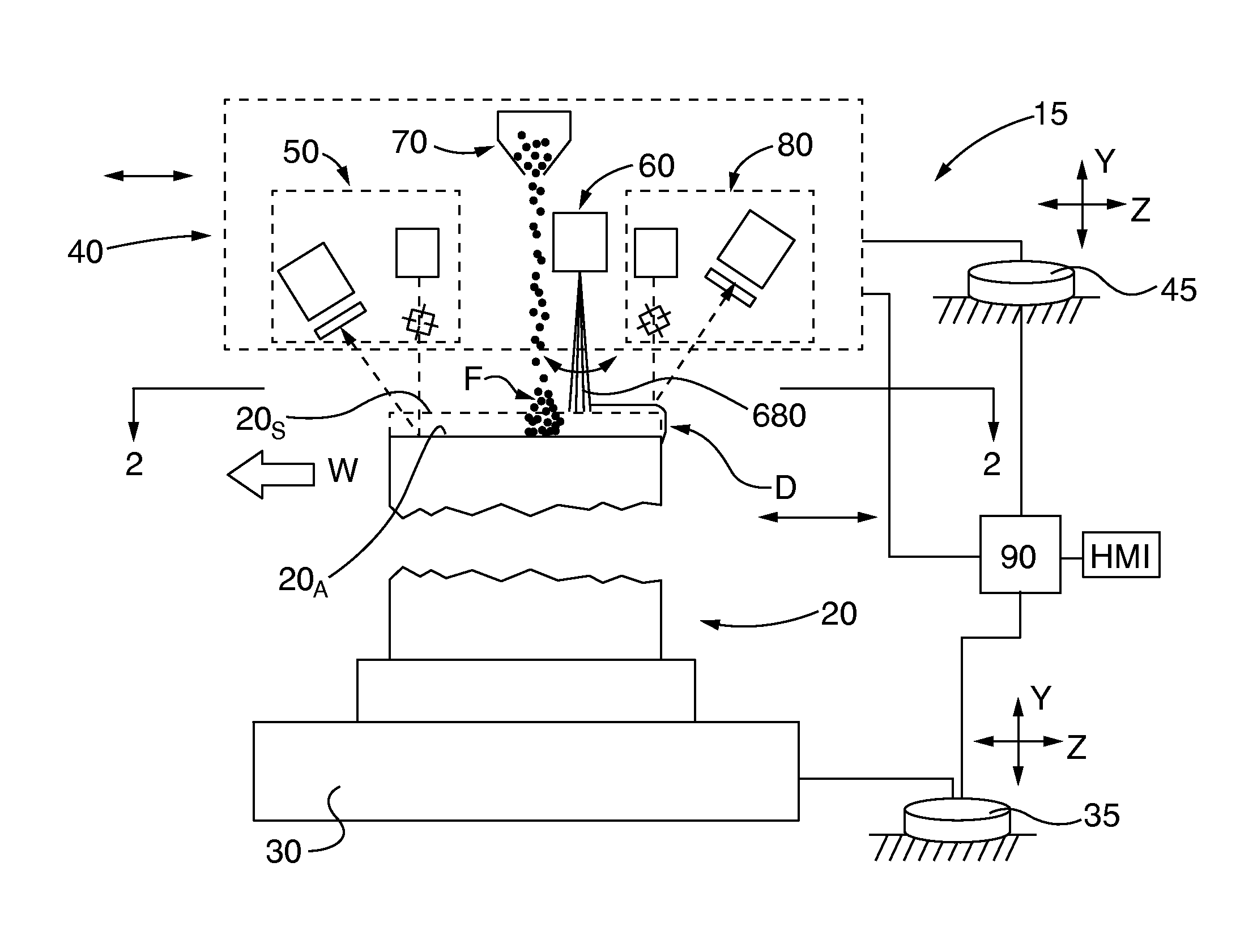
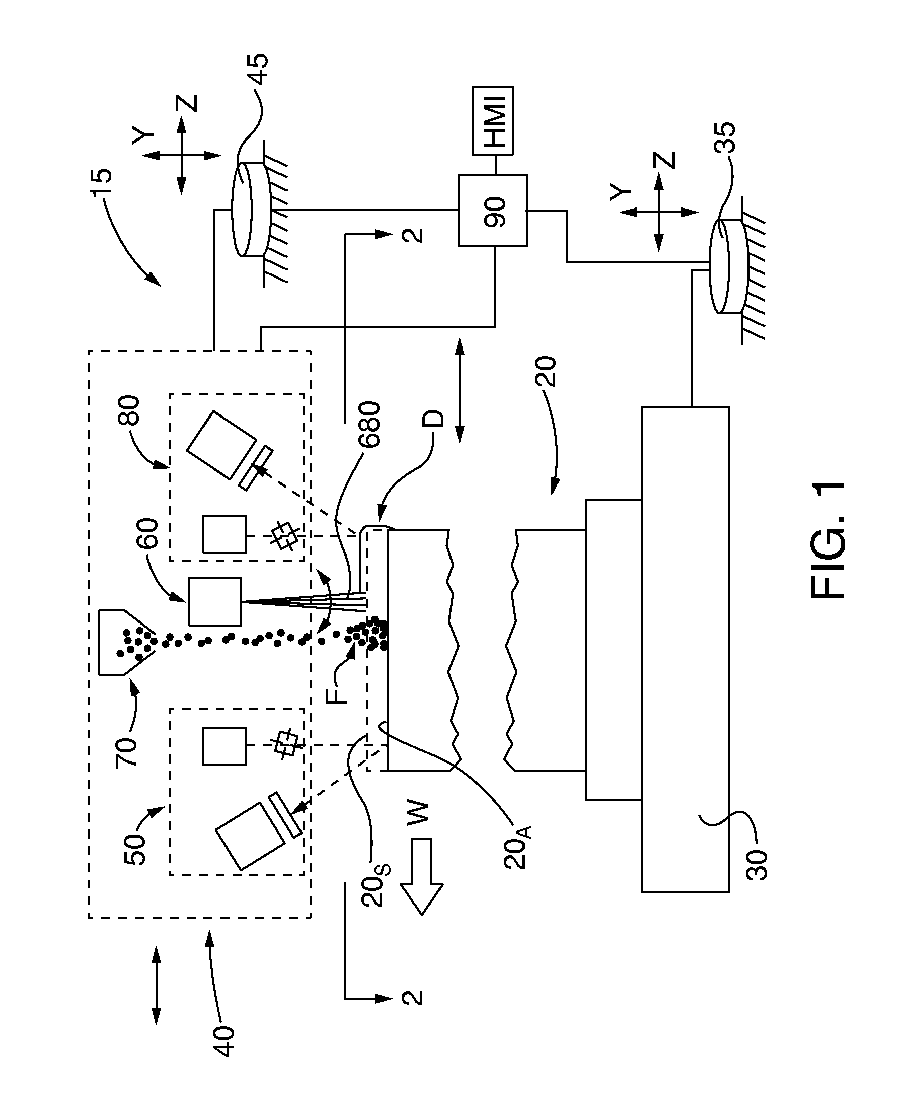
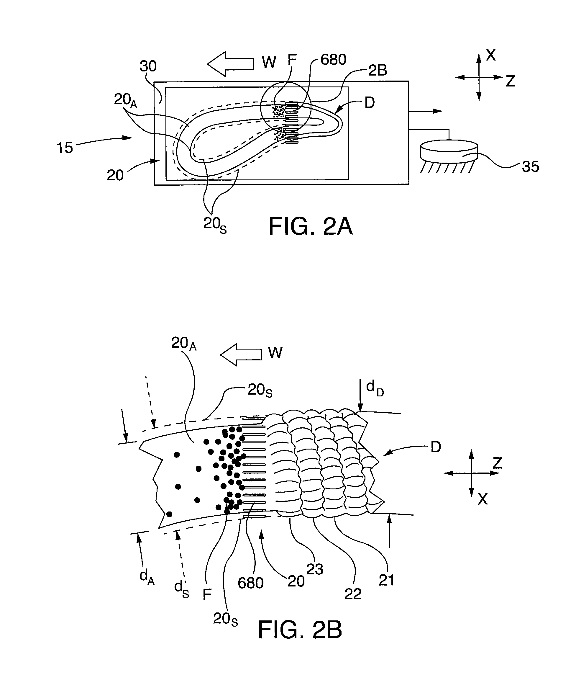
[0041]After considering the following description, those skilled in the art will clearly realize that the teachings of the present invention can be readily utilized in laser cladding systems or methods, wherein turbine components, such as service-degraded superalloy turbine blades and vanes, are clad by laser beam welding. The welding / cladding path, including cladding application profile, is determined by prior, preferably dynamic real time, non-contact 3D dimensional scanning of the component and comparison of the acquired dimensional scan data with specification dimensional data for the component. A welding path for cladding the scanned component to conform its dimensions to the specification dimensional data is determined. The laser welding apparatus, preferably in cooperation with a cladding filler material distribution apparatus, executes the welding path to apply the desired cladding profile.

[0042]In some embodiments described herein a post-weld non-contact 3D dimensional scan...


PUM


Abstract

Superalloy components, such as service-degraded turbine blades and vanes, are clad by laser beam welding. The welding/cladding path, including cladding application profile, is determined by prior, preferably real time, non-contact 3D dimensional scanning of the component and comparison of the acquired dimensional scan data with specification dimensional data for the component. A welding path for cladding the scanned component to conform its dimensions to the specification dimensional data is determined. The laser welding apparatus, preferably in cooperation with a cladding filler material distribution apparatus, executes the welding path to apply the desired cladding profile. In some embodiments a post-weld non-contact 3D dimensional scan of the welded component is performed and the post-weld scan dimensional data are compared with the specification dimensional data. Preferably the welding path and/or cladding profile application are modified in a feedback loop with the pre- and/or post-welding 3D dimensional scanning.

Description

CROSS-REFERENCE TO RELATED APPLICATIONS[0001]This application claims the benefit of priority to commonly owned, co-pending United States utility patent application entitled “SUPERALLOY LASER CLADDING WITH SURFACE TOPOLOGY ENERGY TRANSFER COMPENSATION”, filed Sep. 12, 2012 and assigned Ser. No. 13 / 611,034; United States utility patent application entitled “LASER CLADDING SYSTEM FILLER MATERIAL DISTRIBUTION APPARATUS”, filed Sep. 12, 2012 and assigned Ser. No. 13 / 611,144; and United States utility patent application entitled “METHOD FOR AUTOMATED SUPERALLOY LASER CLADDING WITH 3D IMAGING WELD PATH CONTROL, filed concurrently herewith, Serial Number unknown, Docket Number 2013P06709US / 2012E26552US, all of which are incorporated by reference herein.BACKGROUND OF THE INVENTION[0002]1. Field of the Invention[0003]The invention relates to systems or methods for cladding superalloy components, such as service-degraded turbine blades and vanes, by laser beam welding. The welding / cladding pat...

Claims


Application Information

Patent Timeline
IPC IPC(8): B23K26/34
CPCB23K26/345B23K26/342B23K26/082B23K26/34B23K35/0244B23K2101/001B23P6/007F01D5/28F01D5/286F01D5/288
Inventor BRUCK, GERALD J.KAMEL, AHMED
Owner SIEMENS ENERGY INC
Why Eureka
Try Eureka