Method of energy and power management in dynamic power systems with ultra-capacitors (super capacitors)

a technology of super capacitors and dynamic power systems, applied in the direction of motor/generator/converter stoppers, dynamo-electric converter control, energy-saving board measures, etc., can solve the problems of large peak power demands and regenerative power characteristics of actuators, excessive generator sizing, undesirable current and voltage transients, etc., to maximize the capture of regenerative energy, minimize main power supply size, and extend the life of energy storage elements

Inactive Publication Date: 2014-03-27
EATON CORP
View PDF0 Cites 64 Cited by
  • Summary
  • Abstract
  • Description
  • Claims
  • Application Information

AI Technical Summary

Benefits of technology

[0012]It is desirable for a power management system to maximize the capture of regenerative energy, minimize main power supply size, and extend the life of energy storage elements in the system. Such a power management system may include an ultracapacitor and a charge shuttle comprising a power converter and a controller. The charge shuttle may be coupled with the ultracapacitor and may be configured to be coupled with a load. The charge shuttle may be configured to monitor one or more parameters of the load and the ultracapacitor. The controller may be configured to control energy flow between the load and the ultracapacitor based on or according to one or more monitored parameters. The system may further include a second energy storage element coupled to the charge shuttle. The second energy storage element may be a battery or other source capable of providing energy for a longer duration than the ultracapacitor. The charge shuttle may be further configured to monitor one or more parameters of the second energy storage element. The controller may be further configured to control energy flow to and from the second energy storage element. The charge shuttle may be configured to perform charge balancing between the ultracapacitor and the second energy storage element. The charge shuttle may also be configured to direct regenerative energy from the load to the ultracapacitor or to the second energy storage element.

Problems solved by technology

These increasingly-numerous actuators have significant peak power demands and regenerative power characteristics.
When the demand for power is low (or energy cost is low), available excess generator capacity is stored in batteries (or pumped storage) and is later released during high power demand or at times of high energy cost.
Peak power shaving can, however, have multiple drawbacks or challenges, including excessive generator sizing, undesirable current and voltage transients, and a reduced battery lifespan associated with high stress and high utilization.
Conventional peak power shaving systems and other typical electric power systems may, however, be inadequate for the MEA concept for one or more reasons.
First, the energy sources and distribution networks in typical systems commonly must be oversized to meet peak power requirements at a duty cycle of much less than 50%, resulting in an expensive, heavy, and excessively large solution.
Second, typical systems do not effectively accommodate regenerative loads.
This solution reduces efficiency, adds bulky components, and is not suitable in applications where heat removal is difficult (e.g., MEA, Hybrid Electric Vehicle (HEV), Plug-in Hybrid Electric Vehicle (PHEV)).
But an ultracapacitor used alone can be impractical for at least two reasons.
First, load current is actually not symmetrical.
Second, an ultracapacitor 14 (or bank of ultracapacitors) that could provide the required energy capacity on its own would be both extremely large and extremely expensive.
A potential drawback of such a system is that, if the system requires that either the ultracapacitor or the battery be capable of supporting the load independently (which is often the case), both DC-to-DC converters must be sized to meet the maximum load current.
With larger loads, both converters must support a large current, which can result in a large, overly complex, and / or expensive system.

Method used


Image

  • Method of energy and power management in dynamic power systems with ultra-capacitors (super capacitors)
  • Method of energy and power management in dynamic power systems with ultra-capacitors (super capacitors)
  • Method of energy and power management in dynamic power systems with ultra-capacitors (super capacitors)

Examples


first embodiment

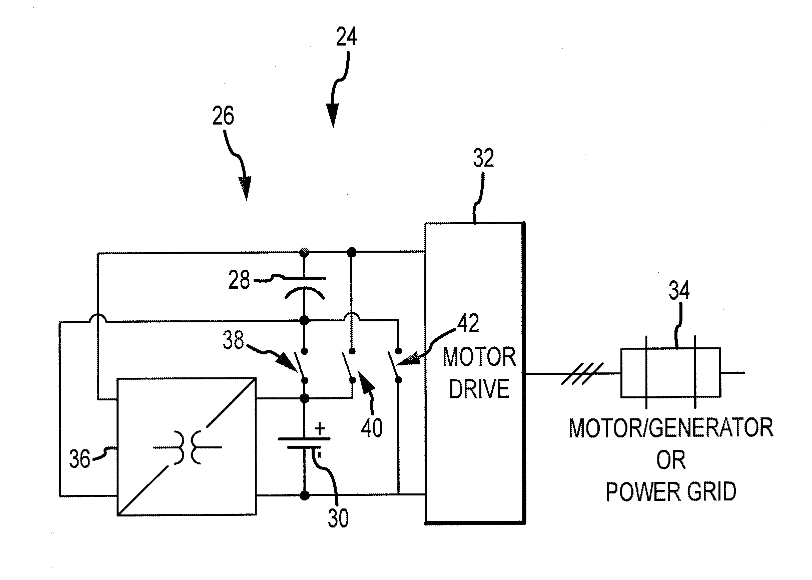
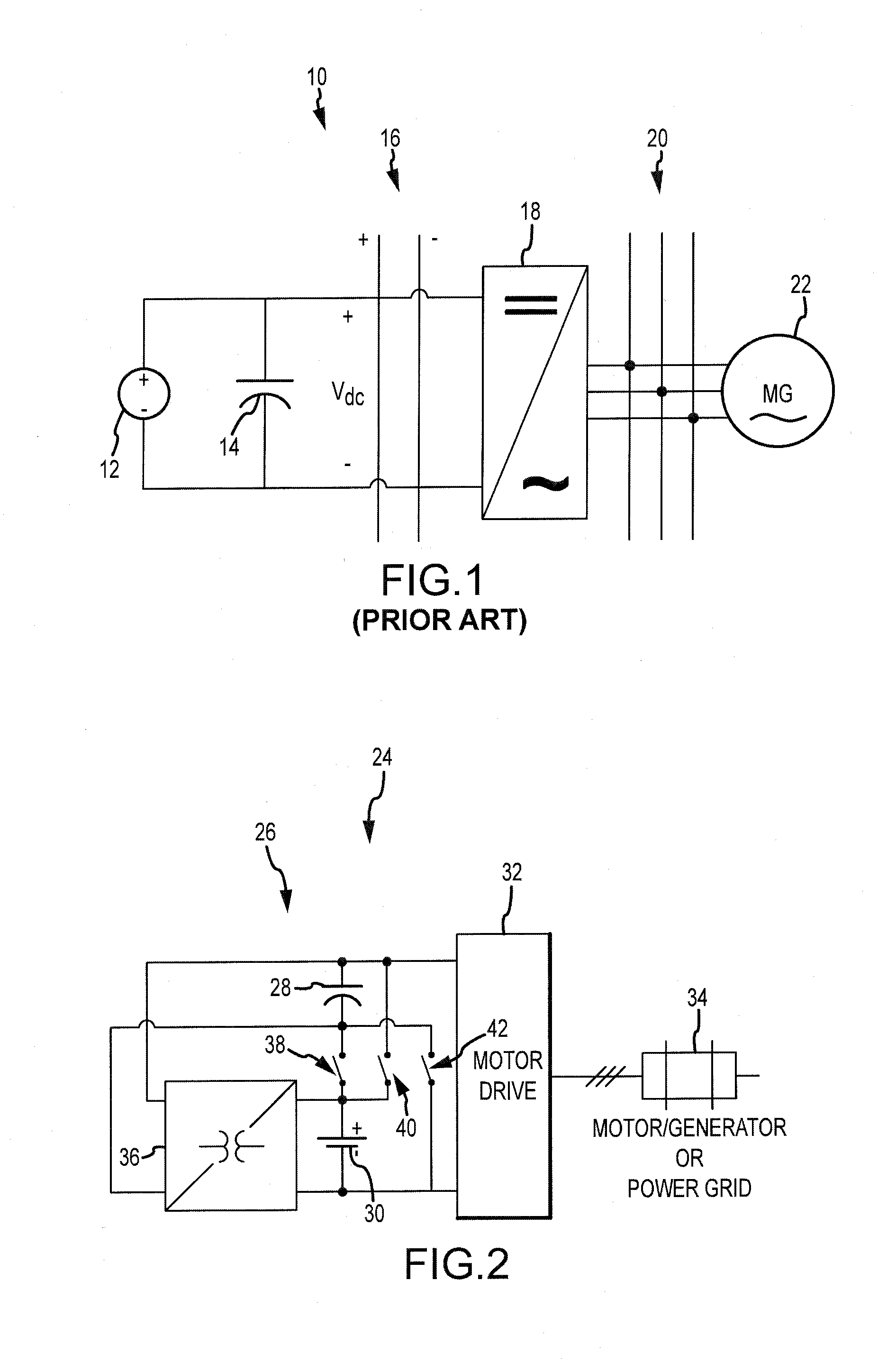
[0028]FIG. 2 is a diagrammatic view generally illustrating a power management system 24 in accordance with teachings of the present disclosure. Illustrated system 24 includes a charge shuttle 26, an ultracapacitor 28, a battery 30, a motor drive 32 that is connected to the system via DC link, and a load 34. As generally illustrated, the charge shuttle 26 may include a power converter 36 and a plurality of switches 38, 40, 42. The charge shuttle 26 may also include a controller (not shown) configured to actuate switches 38, 40, 42 and to control the direction of energy flow through converter 36.

[0029]Load 34 may include, for example only, a motor / generator such as may be used in a More Electric Aircraft (MEA), Hybrid Electric Vehicle (HEV), or Plug-in Hybrid Electric Vehicle (PHEV). The motor / generator may include various components, such as regenerative and non-regenerative loads, energy sources (e.g., mechanically driven generators, fuel cells), and distribution networks. The motor...

second embodiment

[0038]FIG. 6 is a diagrammatic view of a power management system 44. The illustrated system 44 is shown including a generator 46, a main power bus 48, three AC / DC power converters 50a, 50b, 50c, three charge shuttles 26a, 26b, 26c, three ultracapacitors 28a, 28b, 28c, and a battery 30. As illustrated, each charge shuttle 26 may include a respective power converter 51 and a respective controller 53. Illustrated system 44 may further include three loads 52, 54, 56.

[0039]In the illustrated system 44, generator 46 and battery 30 are the “main” power supplies for the system 44. For example only, in a hybrid-electric vehicle (HEV) embodiment, generator 46 may be driven by the gasoline engine, and battery 30 may be the main vehicle battery or bank of batteries. Generator 46 can be configured to provide power to main power bus 48, from which system 44 draws power, as may a larger system and / or other sub-systems.

[0040]Loads 52, 54, 56 may have different characteristics. For example, load 52 ...

third embodiment

[0043]FIG. 7 is a diagrammatic view of a power management system 58. The illustrated system 58 includes is shown including two ultracapacitors 28a, 28b, two batteries 30a, 30b, a charge shuttle 26 (which includes a power converter 36 and a controller 53), a drive controller 60, and a motor / generator 62.

[0044]Drive controller 60 may be configured to control the torque applied to one or more loads of motor / generator 62. Drive controller 60 may also facilitate a field weakening current for motor / generator 62. In an embodiment (e.g., when motor / generator 62 includes a PMSM), a field weakening current may be required to produce torque at speeds above a pre-determined threshold. Such a field weakening current may be reactive and may not produce any real power except for losses in semiconductors, electrical machines, and energy sources.

[0045]In embodiments, batteries 30 and ultracapacitors 28 can serve as storage elements to store energy recaptured from motor / generator 62 for later use by ...


PUM


Abstract

A power management system includes an ultracapacitor and a charge shuttle including a power converter. The charge shuttle may be coupled with the ultracapacitor and may be configured to be coupled with a load. The charge shuttle can be configured to monitor one or more parameters of the load and the ultracapacitor, and to control energy flow between the load and the ultracapacitor based on or according to monitored parameters. The system may also include a battery or other rechargeable energy storage element.

Description

CROSS-REFERENCE TO RELATED APPLICATIONS[0001]This application is a national stage filing based upon International PCT Application No. PCT / US2011 / 044607, with an international filing date of Jul. 20, 2011, which claims the benefit of the filing date of U.S. Provisional Patent Application Ser. No. 61 / 365,986, filed Jul. 20, 2010, the entire disclosures of which are incorporated herein by reference.BACKGROUND[0002]1. Technical Field[0003]The present disclosure relates generally to power management for motor loads and actuation systems, including power management systems using ultracapacitors and other energy storage devices for systems with regenerative loads and peak power demands.[0004]2. Description of the Related Art[0005]Electric power systems on modern vehicles (air, ground or marine), as well as small “islanded” power systems, may be considered “micro-grids” of generators and loads. Such microgrids consist of energy sources (e.g., mechanically driven generators, solar power modu...

Claims


Application Information

Patent Timeline
Patent Type & Authority Applications(United States)
IPC IPC(8): H02J1/10H02P3/14H02P6/00
CPCH02J1/102H02P3/14H02P6/001B64D2221/00H02P6/34B60L50/40Y02T10/70Y02T50/50
Inventor BHAVARAJU, VIJAYFAMILIANT, YAKOV L.SCHMALZ, STEVEN C.
Owner EATON CORP
Why Eureka
Try Eureka