
System And Method For Wireless Power And Data Transmission In A Rotary Steerable System

a technology of rotary steerable system and wireless power, which is applied in the direction of resistance/reactance/impedence, instruments, constructions, etc., can solve the problems of high operating cost, high quality factor, and difficulty in retraction of drill string to repair a failed bha

Inactive Publication Date: 2014-03-27
SCHLUMBERGER TECH CORP
View PDF13 Cites 91 Cited by
  • Summary
  • Abstract
  • Description
  • Claims
  • Application Information

AI Technical Summary

Benefits of technology

The patent describes a way to transfer power and data between a cartridge and a drill collar using magnetic fields. The technology allows for rotation between the cartridge and the drill collar without affecting the magnetic coupling, and efficient transfer of power from coils to sensors and electronics. Additionally, the patent suggests using a retrievable MWD tool to power drill collar sensors, which involves an inner and outer coil with ferrites cores, and the transfer of power through the magnetic field. This technology also allows for data transfer between the drill collar and electronics inside the collar.

Problems solved by technology

Failure of a BHA, whether mechanically or electrically, inevitably brings about expensive and unwelcomed operating costs as the drilling process may be halted and the drill string retracted from the bore so that the failed BHA can be repaired.
In many cases, retraction of a drill string to repair a failed BHA can be very costly.
A common failure point for BHAs is the point of connection from tool to tool, which is naturally prone to failure from adverse fluid ingress and / or misalignment between adjacent tools.
For instance, in many cases, the transmission of power and / or communications data from a rotary steering system to equipment residing in a drill collar is particularly challenging.
In such an application, power and / or communications data transmission via wire can be impractical if not impossible because the drill collar is configured to rotate with respect to the rotary steering system.

Method used


Image

  • System And Method For Wireless Power And Data Transmission In A Rotary Steerable System
  • System And Method For Wireless Power And Data Transmission In A Rotary Steerable System
  • System And Method For Wireless Power And Data Transmission In A Rotary Steerable System

Examples


embodiment 230

[0057]Turning now to FIGS. 5A and 5B, a cross sectional view of two coils 232, 234 is illustrated in FIG. 5A and a side view of the two coils 232, 234 is illustrated in FIG. 5B. In these two figures, a transmitting coil 232 inside a receiving coil 234 of a particular embodiment 230 is depicted. The transmitting coil 232 includes a ferrite rod core 235 that, in some embodiments, may be about 12.5 mm (about 0.49 inch) in diameter and about 96 mm (about 3.78 inches) long with about thirty-two turns of wire 237. Notably, although specific dimensions and / or quantities of various components may be offered in this description, it will be understood by one of ordinary skill in the art that the embodiments are not limited to the specific dimensions and / or quantities described herein.

[0058]Returning to FIG. 5, the receiving coil 234 may include an insulating housing 236, about twenty-five turns of wire 239, and an outer shell of ferrite 238. The wall thickness of the ferrite shell 238 in the ...

embodiment 264

[0066]Turning to FIG. 13, AC power can be passed through the coils. Input AC power at frequency f1 is converted to resonant frequency f0 by a frequency convertor. Normally this would be a step up convertor with f0>>f1. The receiver circuit outputs power at frequency f0, which is converted back to AC power at frequency f1. Alternatively, as one of ordinary skill in the art recognizes, the FIG. 13 embodiment 264 could be modified to accept DC power in and produce AC power out, and vice versa.

[0067]In lieu of, or in addition to, passing power, data signals may be transferred from one coil to the other in certain embodiments by a variety of means. In the above example, power is transferred using an about 100.0 kHz oscillating magnetic field. It is envisioned that this oscillating signal may also be used as a carrier frequency with amplitude modulation, phase modulation, or frequency modulation used to transfer data from the transmitting coil to the receiving coil. Such would provide a o...


PUM

PropertyMeasurementUnit
electrical poweraaaaaaaaaa
poweraaaaaaaaaa
self-inductancesaaaaaaaaaa

Abstract

Various embodiments for wireless power and data communications transmissions between a cartridge in a rotary steering system and components within a drill collar are disclosed. In a certain embodiment, magnetic fields are used to transfer power and data between the cartridge of a rotary steering system and electronics and / or sensors mounted in the drill collar. A first coil is attached to the pressure housing of the cartridge by a shaft containing wires. The turbine in the pressure housing provides an alternating current to the first coil, which is attached to the shaft. Consequently, the first coil generates an alternating magnetic field that passes through the ferrite surrounding a second coil that is attached by wires to an annular pressure housing that is attached to the drill collar. The alternating magnetic field generates an emf in the second coil, which provides power for electronics and sensors mounted in the drill collar.

Description

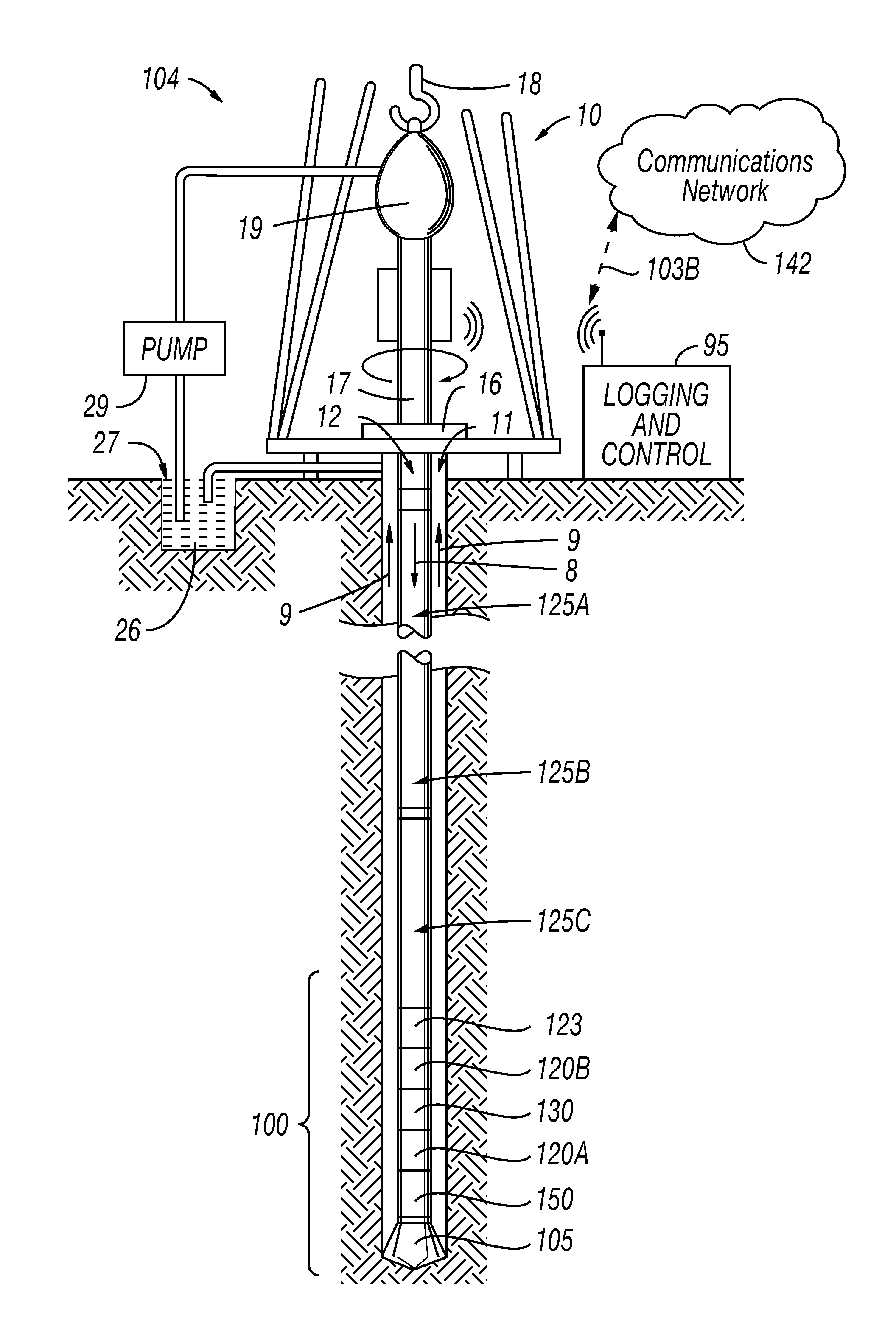
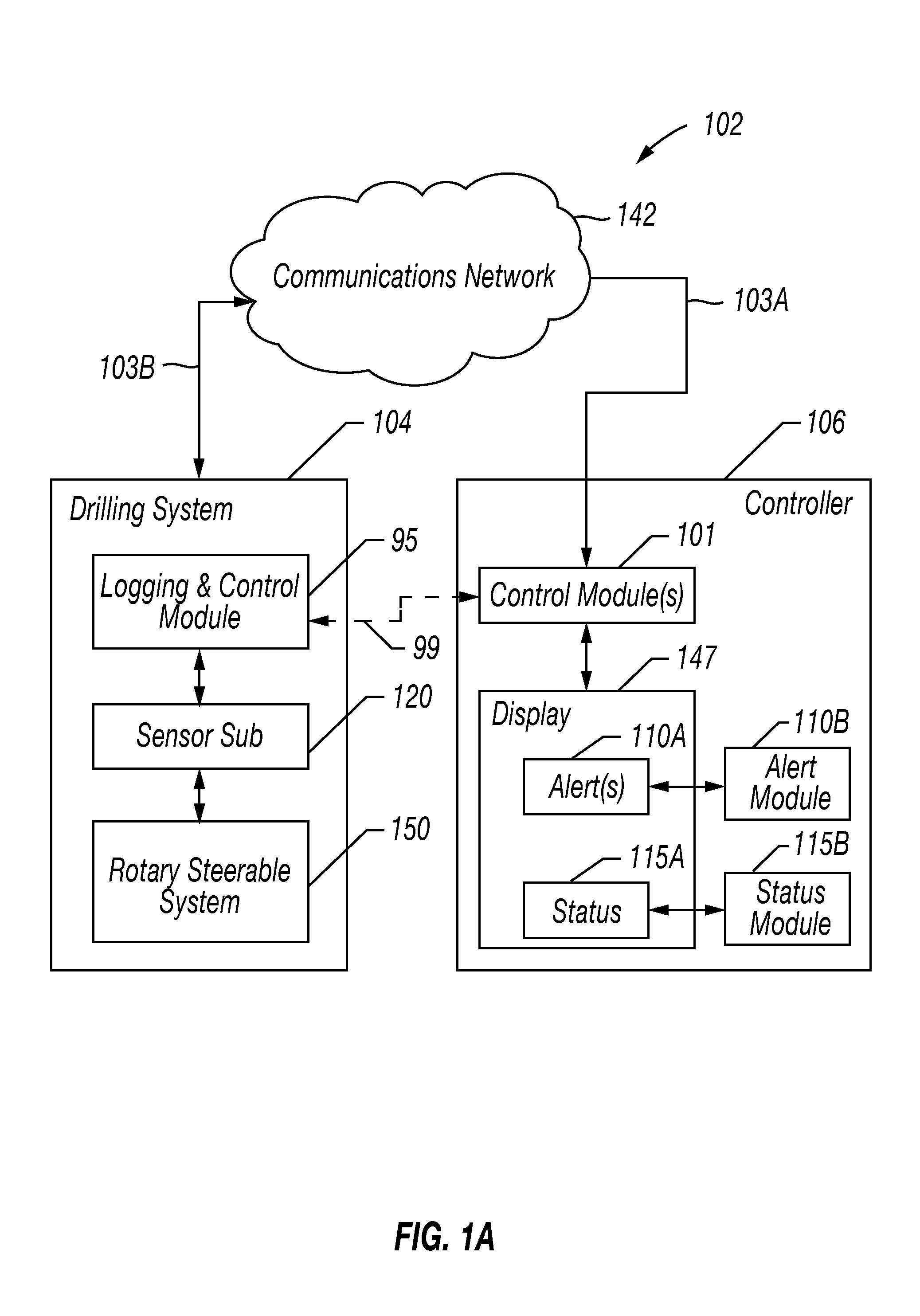
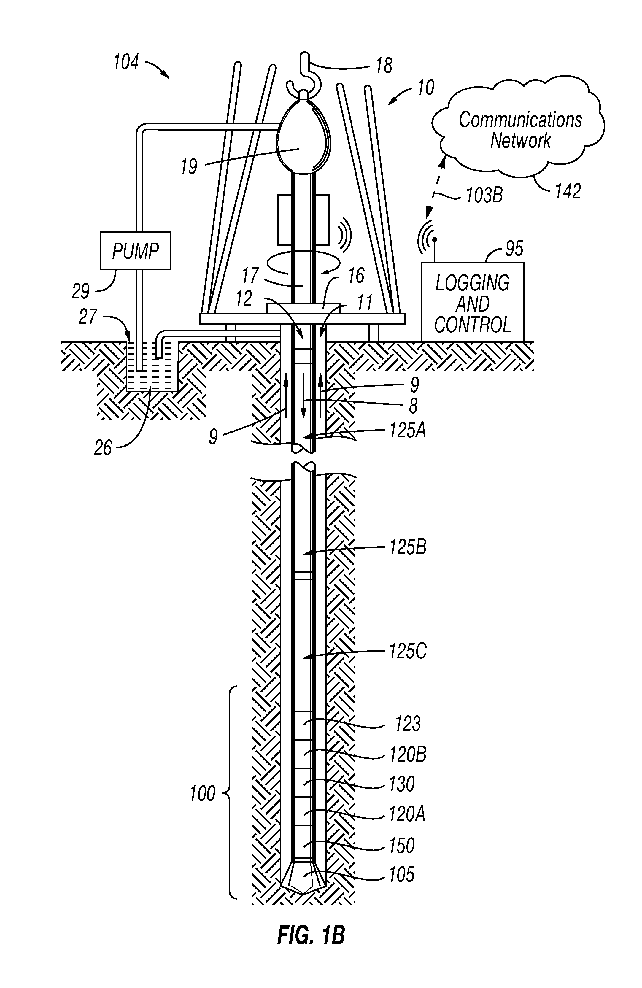
CROSS-REFERENCE TO RELATED APPLICATIONS[0001]This application claims the benefit of and priority to U.S. Provisional Patent Application Ser. No. 61 / 704,910, entitled “System And Method For Wireless Power And Data Transmission In A Bottom Hole Assembly,” and filed on Sep. 24, 2012, U.S. Provisional Patent Application Ser. No. 61 / 704,805, entitled “System And Method for Wireless Power And Data Transmission In A Mud Motor,” and filed on Sep. 24, 2012, and U.S. Provisional Patent Application Ser. No. 61 / 704,758, entitled “Positive Displacement Motor Rotary Steerable System And Apparatus,” and filed on Sep. 24, 2012, the disclosures of which are hereby incorporated by reference in their entireties.DESCRIPTION OF THE RELATED ART[0002]Bottom hole assemblies (“BHA”) at the end of a typical drill string used in the drilling and mining industry today may be a complex assembly of technology that includes not only a drill bit, but also an array of serially connected drill string components or t...

Claims


Application Information

Patent Timeline
Patent Type & Authority Applications(United States)
IPC IPC(8): G01N27/02
CPCG01N27/02E21B47/13H02J50/80H02J50/12H02J50/005
Inventor CLARK, BRIAN OLIVERMORIARTY, KEITH A.GADOT, RAPHAEL
Owner SCHLUMBERGER TECH CORP
Learn More