Method and insert for density gradient separation

a density gradient and insert technology, applied in the field of inserts for centrifugation tubes, can solve the problems of difficult recovery of mononuclear cells, limited detection of metastatic cells, and difficult loading of tubes with inserts, and achieve the effect of rapid prototyping

Active Publication Date: 2014-03-27
STEMCELL TECHNOLOGIES
View PDF1 Cites 28 Cited by
  • Summary
  • Abstract
  • Description
  • Claims
  • Application Information

AI Technical Summary

Benefits of technology

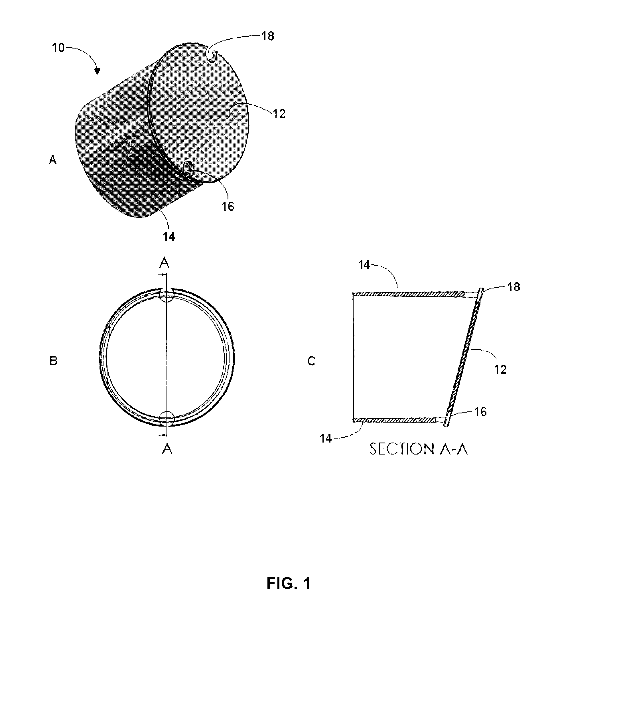
[0102]Inserts with a sloped top member as shown in FIG. 1 without a separate cylindrical support were made out of a silicone stopper. The insert had a thickness of about 5 mm and an angle of around 15° from the horizontal when placed in a vertical 15 mL conical bottom centrifuge tube. The insert was held in place by an interference fit with the sidewall of the centrifuge tube. The insert was positioned in the tube such that when about 5 mL of Ficoll-Paque was added, the liquid level covered the highest point of the insert. Openings were cut out at the highest and lowest points on the stopper. The openings had the shape of a semicircle with a diameter of about 2 mm with the open end of the semicircle facing out from the member.
[0103]The effectiveness of the insert was tested in a standard density gradient separation using a standard 15 mL tube or a 15 mL tube with the insert described above. In each case 5 mL of Ficoll and 3 mL of blood diluted 1:1 with PBS+2% FBS was used. The centrifugal spin was 20 min at 400×g with the brake off.
[0107]3. Pour blood into tube, spin in centrifuge, swirl tube to mix cell-containing buffy coat and pour off.
[0108]Using method 3 above, almost no cells were recovered in the standard tube. This is not surprising since the blood mixed with the Ficoll and did not form a layer of different density for the cells to settle to during centrifugation. In all other cases there were similar numbers of cells recovered as shown in Table 2.
[0109]The phenotype of the recovered cells was analyzed based on light scatter in a flow cytometer. Using methods 2 and 3, where the cell sample was poured onto the Ficoll, there was about 10% granulocyte contamination of the recovered cells compared to 1% for the standard method. This was independent of the presence of the insert. The insert therefore allows for density gradient separation without careful sample layering and buffy layer removal. The higher granulocyte content of the recovered sample observed for methods 2 and 3 may be due to some cells sticking to the surface of the insert or getting trapped in irregularities on the surface. The irregularities on the surface exist because the inserts were cut manually from silicone stoppers using a knife. This would not be expected for a smooth insert.
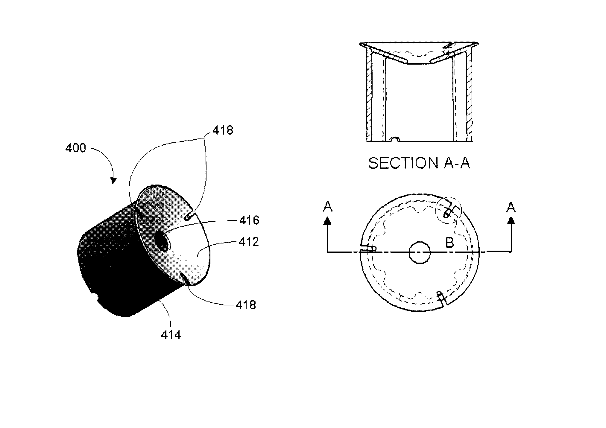
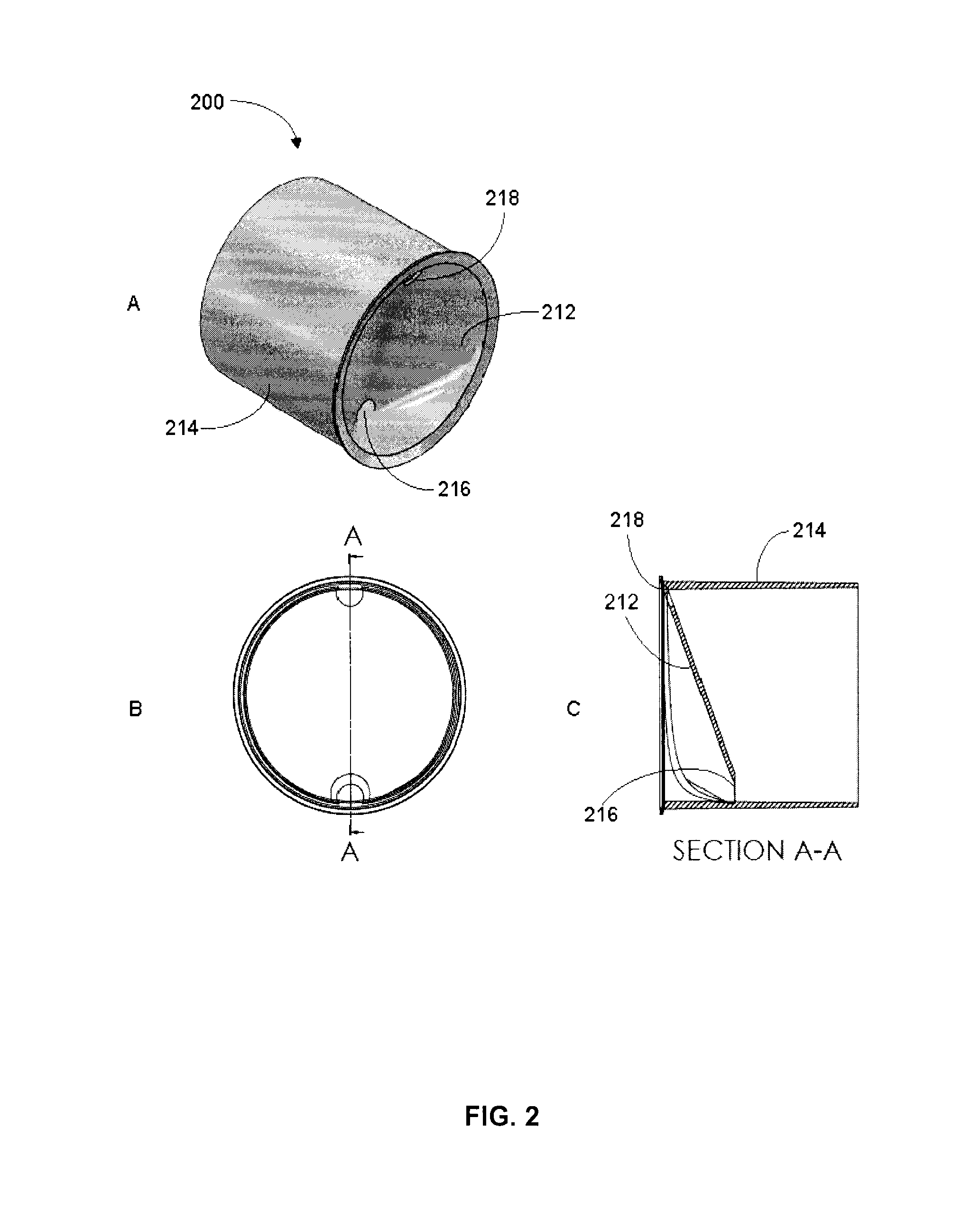
[0110]Inserts as shown in FIGS. 1 to 4 were fabricated of resin using stereolithography methods designed for rapid prototyping. All four inserts were designed to have a form compatible with injection molding, to fit into a standard 50 mL centrifuge tube (e.g. Falcon brand tube) such that the bottom of the insert would sit on the top part of the conical section of the tube and to allow filling of the volume under the insert with density gradient media without requiring centrifugation. Each of the inserts has a small opening at the highest point on the insert so that air can escape as liquid flows in through the large opening located lower on the insert. Each insert was designed so that it would be completely submerged when the tube was filled with approximately 20 mL of Ficoll.

Problems solved by technology

Furthermore, serious complications and indeed the success of a transplant procedure is to a large degree dependent on the effectiveness of the procedures that are used for the removal of cells in the transplant that pose a risk to the transplant recipient.
The ability to detect such metastatic cells is limited by the effectiveness of tissue or fluid sampling and the sensitivity of tumor detection methods.
After centrifugation, if the interface between the plasma and Ficoll is disturbed during handling of the tube, it may be difficult to recover the mononuclear cells without also collecting some erythrocytes and granulocytes.
Tubes with this insert are difficult to load with Ficoll as they require a centrifugation step, and the mesh can get clogged with cells.
The tubes are expensive and the gel can get clogged by cells, especially if there is any immunorosetting of the erythrocytes.

Method used


Image

  • Method and insert for density gradient separation
  • Method and insert for density gradient separation
  • Method and insert for density gradient separation

Examples


example 1

Density Gradient Separation

[0072]Density gradient separation is a well-known procedure wherein cells are separated into one or more fractions based on differences in the density of the cells. An exemplary protocol for a single discontinuous density gradient separation of cells is outlined below:[0073]1. Fill a centrifuge tube about ⅓ full with density gradient solution (e.g. Ficoll-Paque, Histopaque).[0074]2. Gently layer cell suspension (e.g. whole blood or cell suspension) on top of density gradient solution. It is critical to minimize mixing between the cell suspension and density gradient solution. For whole blood it is recommended to dilute the blood with an equal volume of buffered medium such as phosphate buffered saline (PBS).[0075]3. Centrifuge for 15 minutes at 400×g with the brake off to limit disruption to the interface.[0076]4. Carefully remove the enriched cells from the Ficoll:plasma interface using a pipette. It is sometimes preferable to remove the plasma first to m...

example 2

Immunorosetting Using Ficoll-Paque in Standard Tubes

[0078]An exemplary negative selection protocol for immunorosetting cells from whole peripheral blood using Ficoll-Hypaque is set out below:[0079]1. Add 50 uL antibody composition per mL of whole peripheral blood.[0080]2. Incubate for 20 minutes at room temperature.[0081]3. Dilute sample with an equal volume of phosphate buffered saline (PBS)+2% fetal bovine serum (FBS) and mix gently.[0082]4. Layer the diluted sample on top of Ficoll-Hypaque or layer the Ficoll underneath the diluted sample.[0083]5. Centrifuge for 20 minutes at 1200×g, room temperature, with the brake off.[0084]6. Remove the enriched cells from the Ficoll:plasma interface.[0085]7. Wash enriched cells with 5-10× volume of PBS+2% FBS.

[0086]Optionally, for enrichment of monocytes and other adherent cells, 1 mM EDTA can be added to the sample of whole blood and to all wash / dilution solutions.

example 3

Use of Prior Art Density Gradient Separation Tubes with Inserts

[0087]Accuspin® (available from Sigma-Aldrich), Leucosep® (available from Greiner Bio-One GmbH, Germany), UniSep (available from Novamed, Jerusalem Israel), and ACT Dendreon (previously available from MICRA Scientific, Inc. and described in U.S. Pat. No. 5,840,502) density centrifugation tubes each contain an insert intended to facilitate the loading of sample without disrupting the layer between the separation media and the sample.

[0088]These tubes must be loaded first with the appropriate volume of DSM based on the tube size and location of the insert. Generally, the tubes are then centrifuged for a short period to drive the DSM below the insert. The tubes are then ready to use as in a standard density gradient separation protocol such as set out in Example 1. With these tubes, layering step 2 of Example 1 is simplified by allowing the sample to be added quickly to the DSM since it will only mix with the volume of DSM ...


PUM

PropertyMeasurementUnit
diameteraaaaaaaaaa
diameteraaaaaaaaaa
angleaaaaaaaaaa

Abstract

An insert for a centrifuge tube suitable for use in density gradient separation is described. The insert includes a member sized to fit within the tube for dividing the tube into a top portion and a bottom portion. Optionally the insert has a support extending or depending from the member for positioning the member within the tube. At least two openings are located on the member so that a first opening is closer to a bottom end of the tube relative to a second opening when the insert is positioned in the centrifuge tube. Also described are methods for separating a target population of cells from a sample using the insert for a centrifuge tube.

Description

RELATED APPLICATIONS[0001]This application claims the benefit of priority of co-pending U.S. provisional application No. 61 / 482,886 filed on May 5, 2011, the contents of which are incorporated herein by reference in their entirety.TECHNICAL FIELD[0002]This application relates to a device and method for separating populations of cells and more specifically to an insert for a centrifugation tube and method for separating populations of cells using density gradient separation.INTRODUCTION[0003]In many applications it is desirable to enrich or, alternatively, deplete certain cell populations in a biological sample. The fields of hematology, immunology and oncology rely on samples of peripheral blood and cell suspensions from related tissues such as bone marrow, spleen, thymus and fetal liver. The separation of specific cell types from these heterogeneous samples is key to research in these fields, as well as diagnostics and therapy for certain malignancies and immune / hematopoietic disor...

Claims


Application Information

Patent Timeline
Patent Type & Authority Applications(United States)
IPC IPC(8): G01N33/49B04B7/12G01N33/569C12M1/26
CPCG01N33/491G01N33/56972B04B7/12C12M33/10B01L3/5021B01L2200/0684B01L2300/0618B03D3/00
Inventor WOODSIDE, STEVEN M.
Owner STEMCELL TECHNOLOGIES
Why Eureka
Try Eureka